Vehicle steering apparatus

Inactive Publication Date: 2009-01-29
JTEKT CORP
View PDF12 Cites 13 Cited by
  • Summary
  • Abstract
  • Description
  • Claims
  • Application Information

AI Technical Summary

Benefits of technology

[0006]Accordingly, it is an objective of the present invention to provide a vehicle steering apparatus that ensures

Problems solved by technology

In other words, the damper compensation control hampers quick steering operation.
This deteriorat

Method used


Image

  • Vehicle steering apparatus
  • Vehicle steering apparatus
  • Vehicle steering apparatus

Examples


Example

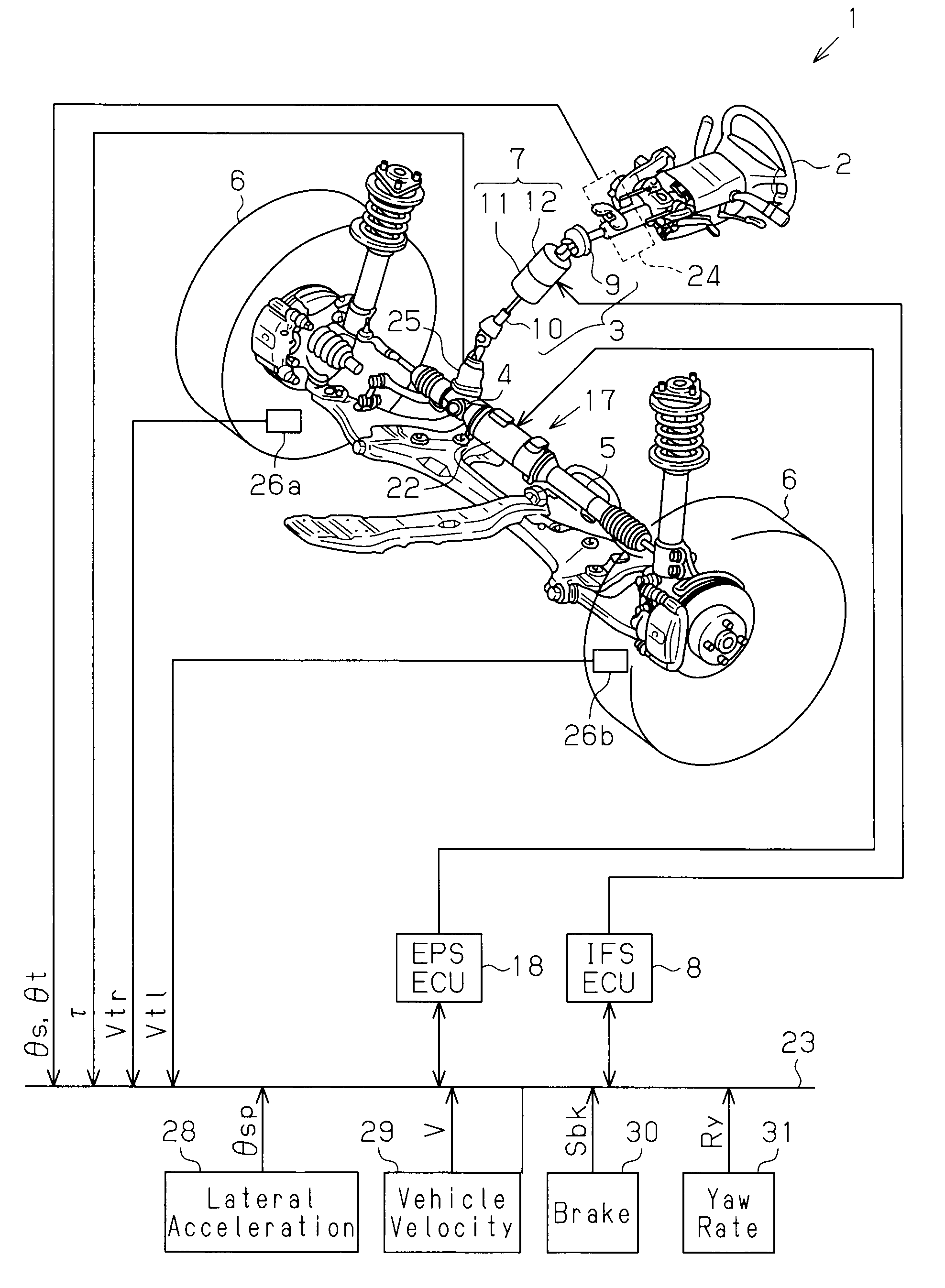
[0019]A vehicle steering apparatus 1 provided with a steering force assist device and a variable transmission ratio device according to one embodiment of the present invention will now be described with reference to drawings.

[0020]FIG. 1 is a schematic diagram showing the structure of the steering apparatus 1 according to the preferred embodiment. As shown in the drawing, a steering shaft 3 to which a steering wheel 2 is fixed is coupled to a rack 5 via a rack and pinion mechanism 4. Rotation of the steering shaft 3 accompanying a steering operation is converted to a reciprocating linear motion of the rack 5 by the rack and pinion mechanism 4. The reciprocating linear motion of the rack 5 changes the steering angle of the steered wheels 6, or the tire angle, thereby changing the traveling direction of the vehicle.

[0021]The vehicle steering apparatus 1 includes a variable gear ratio actuator 7 and an IFS ECU (Intelligent Front Steering Electronic Control Unit) 8. The variable gear ra...


PUM


Abstract

A vehicle steering apparatus 1 includes an EPS actuator 17 and an EPS ECU 18 that controls the EPS actuator 17. The EPS actuator 17 applies an assist force that assists a steering operation. A microcomputer 43 of the EPS ECU 18 determines whether the currently executed oversteer control (OS control) is being intensified or converged. In the OS control intensification state, in which the vehicle stability is low, the microcomputer 43 reduces a damper compensation current command Idp* (Idp**), which is a damper compensation component for attenuating a steering wheel turning speed ωs.

Description

CROSS-REFERENCE TO RELATED APPLICATIONS[0001]This application is based upon and claims the benefit of priority from prior Japanese Patent Application No. 2007-191216, filed on Jul. 23, 2007, the entire contents of which are incorporated herein by reference.BACKGROUND OF THE INVENTION[0002]The present invention relates to a vehicle steering apparatus, and more specifically to a vehicle steering apparatus provided with a steering force assist device.[0003]A typical vehicle steering apparatus includes a steering force assist device that applies to a steering system an assist force for assisting steering operation. An electric power steering apparatus (EPS actuator) using a motor as a drive source has been known as a steering force assist device. The steering force assist device typically executes damper compensation control based on the steering wheel turning speed, thereby improving the steering characteristic. This primarily suppresses excessive steering angle at high speed driving.[...

Claims


Application Information

Patent Timeline
IPC IPC(8): B62D5/04
CPCB62D5/008B62D5/0463B62D6/008B62D6/002B62D5/0472
Inventor KATO, HIROAKIMIKAMO, SATORU
Owner JTEKT CORP
Why Eureka
Try Eureka