Electric power steering apparatus

a technology of electric power steering and steering wheel, which is applied in the direction of gearing, gearing details, hoisting equipment, etc., can solve the problems of prone to accidental deformation of bent leaf springs in the assembly process, and achieve the effect of reducing the amount of backlash and improving the work efficiency in the assembly process

Inactive Publication Date: 2009-04-28
JTEKT CORP
View PDF15 Cites 14 Cited by
  • Summary
  • Abstract
  • Description
  • Claims
  • Application Information

AI Technical Summary

Benefits of technology

[0007]In the electric power steering apparatus that includes the generally α-shaped bent leaf spring for reducing the backlash amount as proposed in Japanese Patent Application Laid-Open No. 2004-203154, however, the bent leaf spring is prone to be accidentally deformed in the assembly process, because of its á-shaped form made of a strip-shaped leaf spring. Furthermore, the bent leaf spring requires the worker's attention on the orientation thereof so as not to assemble the bent leaf spring in a reverse orientation, because the bent leaf spring has to be assembled in a specifically predetermined orientation. Thus, the work efficiency in the assembly process has to be improved.
[0009]The present invention has been achieved in view of the foregoing situation, with a primary object to provide an electric power steering apparatus that employs a coil spring, and allows increasing rotating performance of a pinion and minimizing meshing shift of the pinion with respect to the mating gear wheel.
[0010]A first aspect of the present invention provides an electric power steering apparatus comprising a pinion interlockedly connected to an output shaft of an electric motor, a first and a second bearing each supporting a respective side of the pinion in a housing, and a gear wheel meshed with the pinion and connected to a steering unit so that rotation of the electric motor assists steering operation, wherein the housing includes a fitting bore in which the first bearing supporting a side of the pinion closer to the electric motor is to be fitted, and an annular retaining portion located at a position corresponding to the second bearing and eccentrically oriented with respect to a center of the fitting bore in a direction that shortens a distance between a center of rotation of the pinion and that of the gear wheel, and the annular retaining portion retains a coil spring wound such that an axial center thereof forms a ring-shape around an outer circumference of the second bearing.
[0013]According to the first aspect of the present invention, the annular retaining portion eccentrically oriented in a direction that shortens the distance between the center of rotation of the pinion and that of the gear wheel retains the coil spring, so as to locate the pinion closer to the axial center of an output shaft of the electric motor when the pinion and the gear wheel are meshed with each other. Such configuration can keep the pinion from eccentrically rotating, and also allows applying the elastic restoring force of the coil spring to the pinion on the axial center of the output shaft of the electric motor in a direction orthogonal to the direction of the distance between the centers of rotation, thereby minimizing the meshing shift of the pinion with respect to the gear wheel.
[0014]According to the second aspect of the present invention, the coil spring is fitted in the groove that is eccentrically oriented. Such arrangement allows assembling the coil spring accurately in position, thereby improving the work efficiency in the assembly process of the coil spring.
[0015]According to the third aspect of the present invention, when a reverse input load is applied from the gear wheel to the pinion, the coil spring is warped by such reverse input load so that the pinion is displaced in a direction that extends the distance between the centers of rotation, thereby mitigating the impact of the reverse input load.

Problems solved by technology

In the electric power steering apparatus that includes the generally α-shaped bent leaf spring for reducing the backlash amount as proposed in Japanese Patent Application Laid-Open No. 2004-203154, however, the bent leaf spring is prone to be accidentally deformed in the assembly process, because of its á-shaped form made of a strip-shaped leaf spring.

Method used


Image

  • Electric power steering apparatus
  • Electric power steering apparatus
  • Electric power steering apparatus

Examples


Embodiment Construction

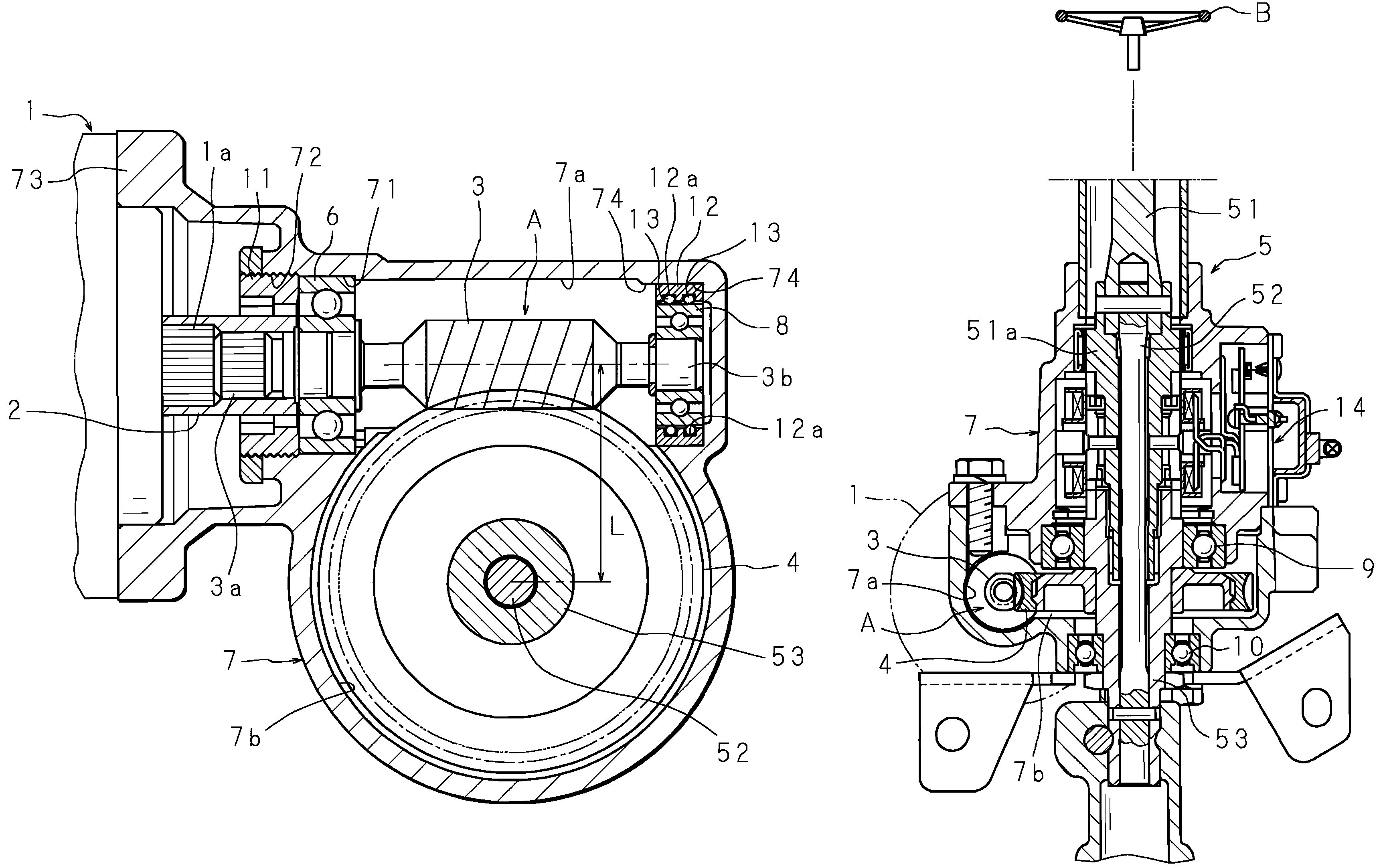
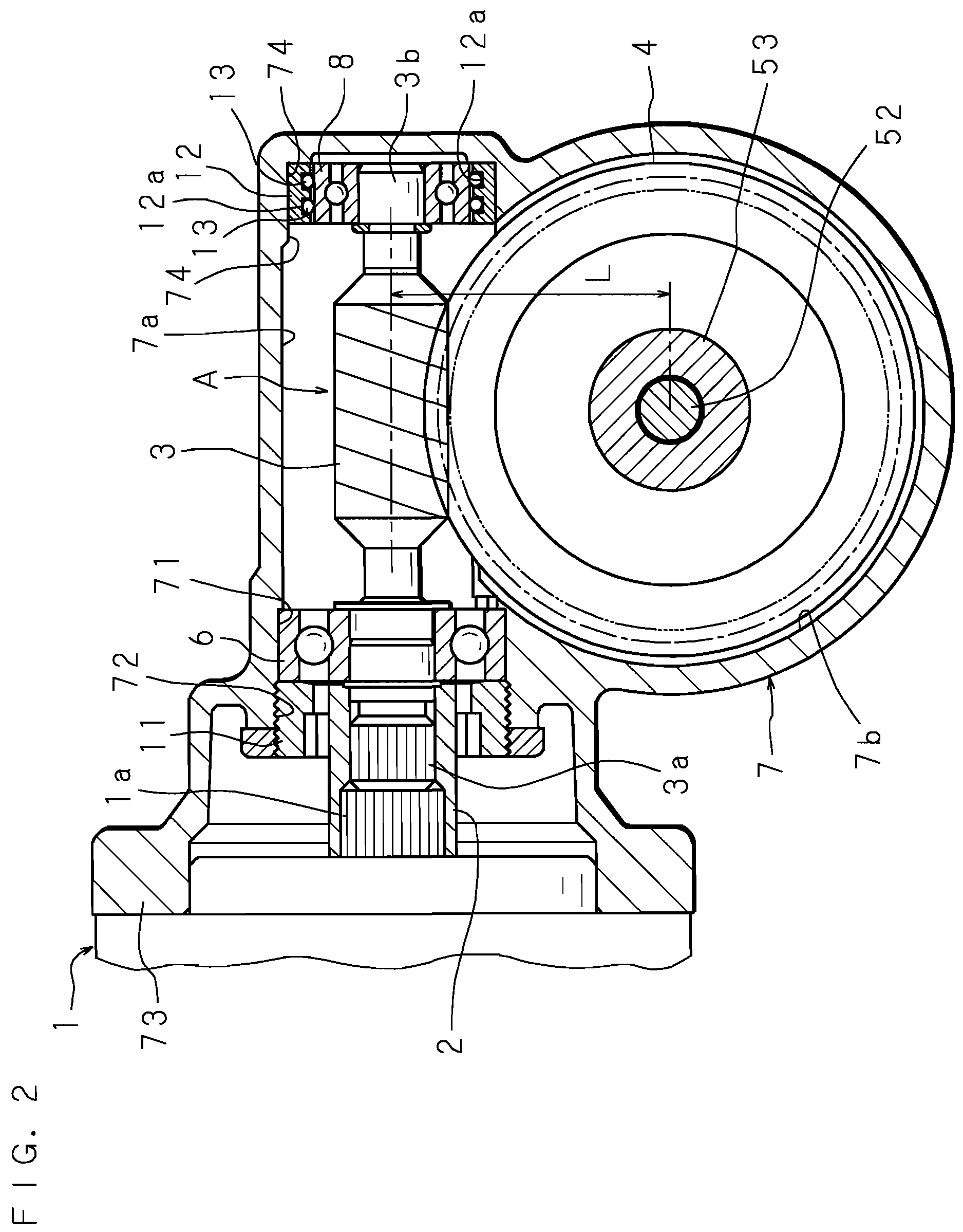
[0025]Hereunder, the present invention will be described in detail based on the drawings illustrating an embodiment thereof. FIG. 2 is a cross-sectional view showing an important portion of an electric power steering apparatus according to the present invention; FIG. 3 is an enlarged fragmentary cross-sectional view of the same; FIG. 4 is a cross-sectional view taken along the line II-II in FIG. 3; and FIG. 5 is a cross-sectional view showing an overall configuration of the electric power steering apparatus.

[0026]The electric power steering apparatus includes an electric motor 1 for steering assistance, a reduction gear mechanism A including a worm 3 connected to an output shaft 1a of the electric motor 1 via a shaft coupling 2 so as to serve as a pinion and a worm wheel 4 meshed with the worm 3 to serve as a gear wheel, and a steering unit 5 connected to the reduction gear mechanism A.

[0027]The steering unit 5 includes a first steering shaft 51 having an upper end portion connected...


PUM


Abstract

An electric power steering apparatus includes a worm interlockedly connected to an output shaft of an electric motor, a first and a second bearing each supporting the respective side of the worm in a housing, and a gear wheel meshed with the worm. The housing includes a fitting bore in which the first bearing supporting a side of the worm closer to the electric motor is to be fitted, and an annular retaining portion located at a position corresponding to the second bearing and eccentrically oriented with respect to the center (axial center) of the fitting bore in a direction that shortens a distance L between the center of rotation of the worm and that of the gear wheel, and the annular retaining portion retains a coil spring around an outer circumference of the second bearing.

Description

CROSS-REFERENCE OF RELATED APPLICATION[0001]This Nonprovisional Application claims priority under 35 U.S.C. §119(a) on Patent Application No. 2006-036871 in Japan on Feb. 14, 2006, the entire contents of which are hereby incorporated by reference.BACKGROUND OF THE INVENTION[0002]The present invention relates to an electric power steering apparatus that employs an electric motor as a generating source of steering assistance force.[0003]An electric power steering apparatus for a vehicle includes an electric motor for steering assistance and a reduction gear mechanism that transmits rotational force of the electric motor to a steering unit, so as to assist the motion of the steering unit with the rotation of the electric motor in response to rotation of a steering means, thereby alleviating the labor imposed on the driver for the steering operation.[0004]The reduction gear mechanism is supported by a pair of bearings each provided on a respective side thereof in a housing, and includes...

Claims


Application Information

Patent Timeline
Patent Type & Authority Patents(United States)
IPC IPC(8): B62D5/04F16H55/24F16H57/021F16H57/028
CPCB62D5/0409F16C27/04F16F1/045F16H55/24F16H57/021F16H57/039F16H1/16F16H2057/0224F16H2057/127F16H2057/0213F16C2326/24F16C2361/61F16C19/06
Inventor IMAGAKI, SUSUMUOUGITA, SHINGOSUGIURA, TOMONORI
Owner JTEKT CORP
Why Eureka
Try Eureka