

Torsional wire treatment drawing system
a drawing system and torsional wire technology, applied in the field of die assembly, can solve problems such as market place problems, and achieve the effect of increasing the ability to remove heat from the system, increasing the drawing speed and die li
- Summary
- Abstract
- Description
- Claims
- Application Information
AI Technical Summary
Benefits of technology
Problems solved by technology
Method used
Image

Examples
Embodiment Construction
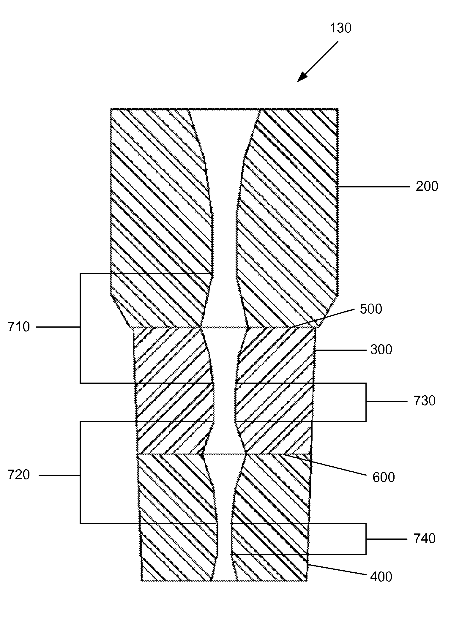
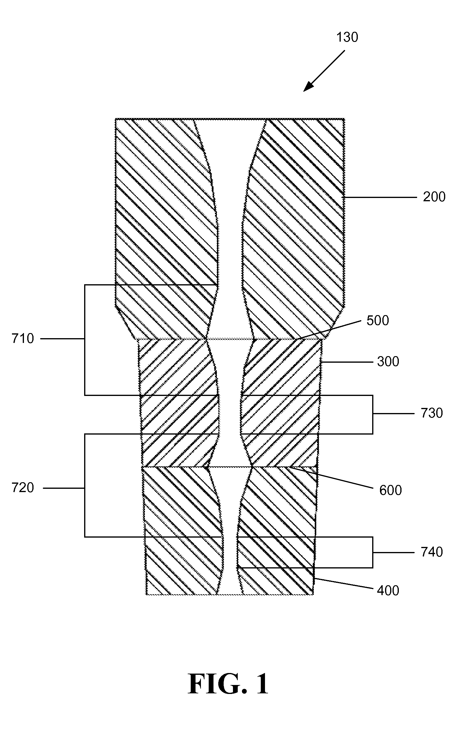
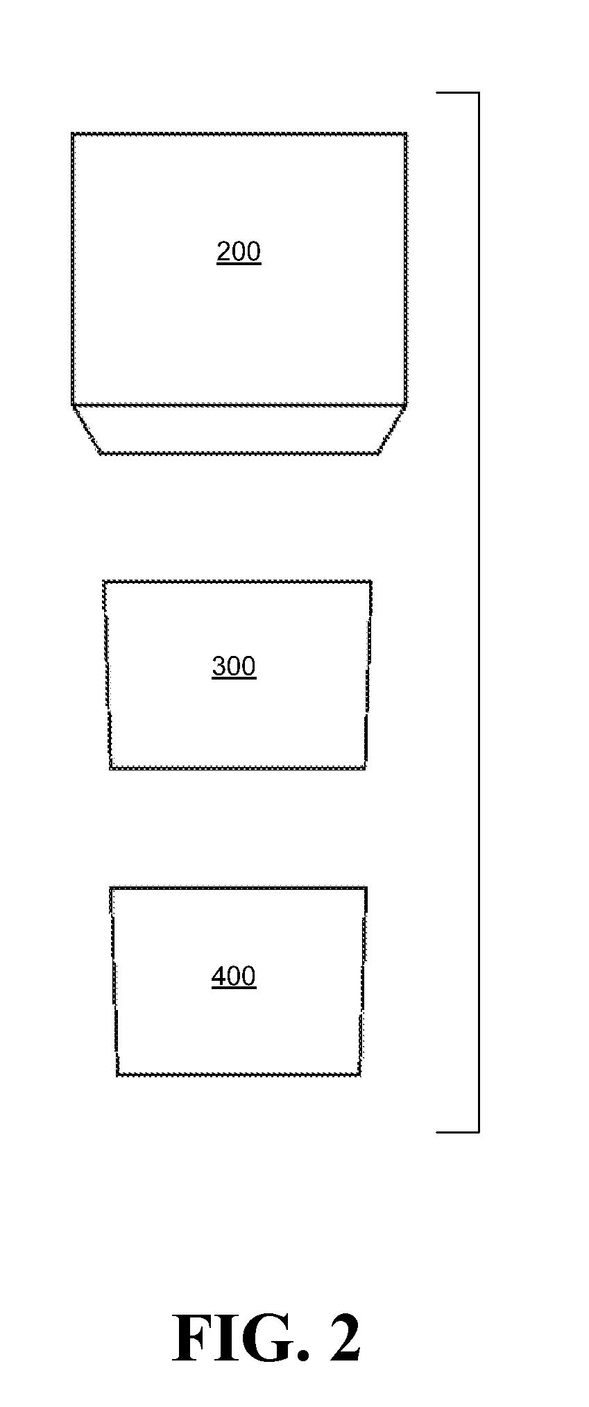
[0095]The present invention will now be described in detail the simplest form of the invention, a three die system comprised of one pressure die and two drawing dies (double drawing dies) with reference to a few preferred embodiments thereof as illustrated in the accompanying drawings. In the following description, numerous specific details are set forth in order to provide a thorough understanding of the present invention. It will be apparent, however, to one skilled in the art, that the present invention may be practiced without some or all of these specific details. In other instances, well known operations have not been described in detail so not to unnecessarily obscure the present invention.
[0096]Referring now to FIG. 1 through FIG. 3B, a wire drawing case 100 for use in a die box (not shown) is comprised of a die cap or male top 110 and a die holder or female bottom 120. The male top 110 comprises or holds in place pressure die 200. The female bottom 120 comprises or holds in...
PUM
| Property | Measurement | Unit |
|---|---|---|
| time | aaaaa | aaaaa |
| pressure | aaaaa | aaaaa |
| diameter | aaaaa | aaaaa |
Abstract
Description
Claims
Application Information