Pattern drawing method and pattern drawing apparatus

a pattern drawing and pattern technology, applied in the direction of electrical equipment, printed circuits, printing, etc., can solve the problems of inability to achieve practical throughput, limitation in the selection of surface tension and viscosity of liquid droplet material, and difficulty in applying surface treatment to non-planar substrates with large level differences or large recessions, etc., to achieve high practical fine pattern drawing techniques, easy heating, and sufficient fine pattern deposition rate

Active Publication Date: 2010-12-02
NAT INST OF ADVANCED IND SCI & TECH
View PDF2 Cites 15 Cited by
  • Summary
  • Abstract
  • Description
  • Claims
  • Application Information

AI Technical Summary

Benefits of technology

[0025]In the present invention, since the liquid droplet size is large, the material supply amount is sufficiently large as compared with that of the fine ink jet technique using the discharge of fine liquid droplets, and hence the deposition rate of the fine pattern is sufficiently high. Thus, when a fine wiring of several tens micrometers or less is formed, it is not necessary to particularly use a nozzle having a minute opening size and the electrostatic suction. Thus, it is possible to draw a fine pattern which is smaller than the nozzle opening diameter or the ink liquid droplet diameter, while using a nozzle having an opening size equal to or larger than 50 μm which is about the opening size of the conventional ink jet nozzle.
[0026]Thereby, it is possible to solve a problem of clogging of raw material ink in a fine nozzle, which has conventionally been a large practical problem. Thus, it is possible to realize a highly practical fine pattern drawing technique.
[0027]Further, it is possible to directly draw a highly dense and thick fine line on various substrate materials, while minimizing the influence of the combination of the substrate with the raw material ink and the influence of the wettability of the raw material ink to the substrate surface, which wettability is based on the surface roughness of the substrate.
[0028]Note that it is conceivable that the same effect can be obtained even in the case where the substrate is directly heated by a heater, or the like. However, in this case, since a large area other than the liquid droplet impact position (impact scheduled region) is heated, and since the ink jet head itself is also easily heated by the heat emitted from the substrate, the raw material ink in the nozzle of the head is dried with the lapse of time, so that the nozzle is clogged by the raw material ink in the nozzle. This results in a problem that stable ink discharge cannot be realized for a long time. Further, this results in a disadvantage that, particularly in the case where the distance between the nozzle and the substrate is reduced to several millimeters or less due to the requirement of drawing precision, and where fine liquid droplets having a diameter of 100 μm or less are discharged, the substrate temperature is difficult to be increased to 100° C. or more.
[0029]On the other hand, when the heating is performed by irradiation of the laser or the infrared ray, the space in the impact scheduled region is locally heated, and hence the thermal influence on the ink jet nozzle set close to the substrate is significantly suppressed. Thus, in the state where the raw material ink in the nozzle is not dried and where no nozzle clogging occurs, the substrate surface can be heated to a sufficiently high temperature, so that the liquid droplet discharge and the drawing can be stably continued.

Problems solved by technology

However, in the case where the various kinds of surface treatment are applied to the substrate surface, there are problems such as that the combination of the liquid droplet material used to perform drawing on the substrate surface with the substrate material is limited, and that the surface treatment is difficult to be applied to a non-planar substrate having a large level difference or having large recessions and projections.
Further, in view of the clogging of the nozzle, there is a limitation in the selection of the surface tension and the viscosity of the liquid droplet material, although the limitation depends on the liquid droplet material to be supplied.
Thus, in order to obtain a film thickness of several micrometers or more, the drawing process needs to be repeated several tens times or more, which results in a practical problem that it takes too much time to draw a wiring for large current power transmission and a wiring for signal transmission in a high frequency range, and hence a practical throughput cannot be obtained.

Method used


Image

  • Pattern drawing method and pattern drawing apparatus
  • Pattern drawing method and pattern drawing apparatus
  • Pattern drawing method and pattern drawing apparatus

Examples


Embodiment Construction

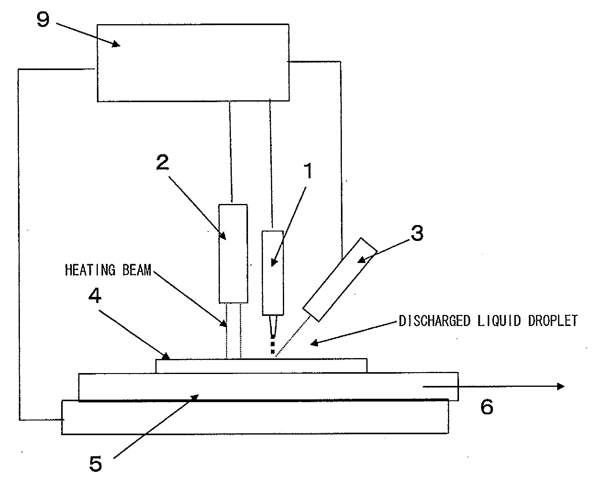
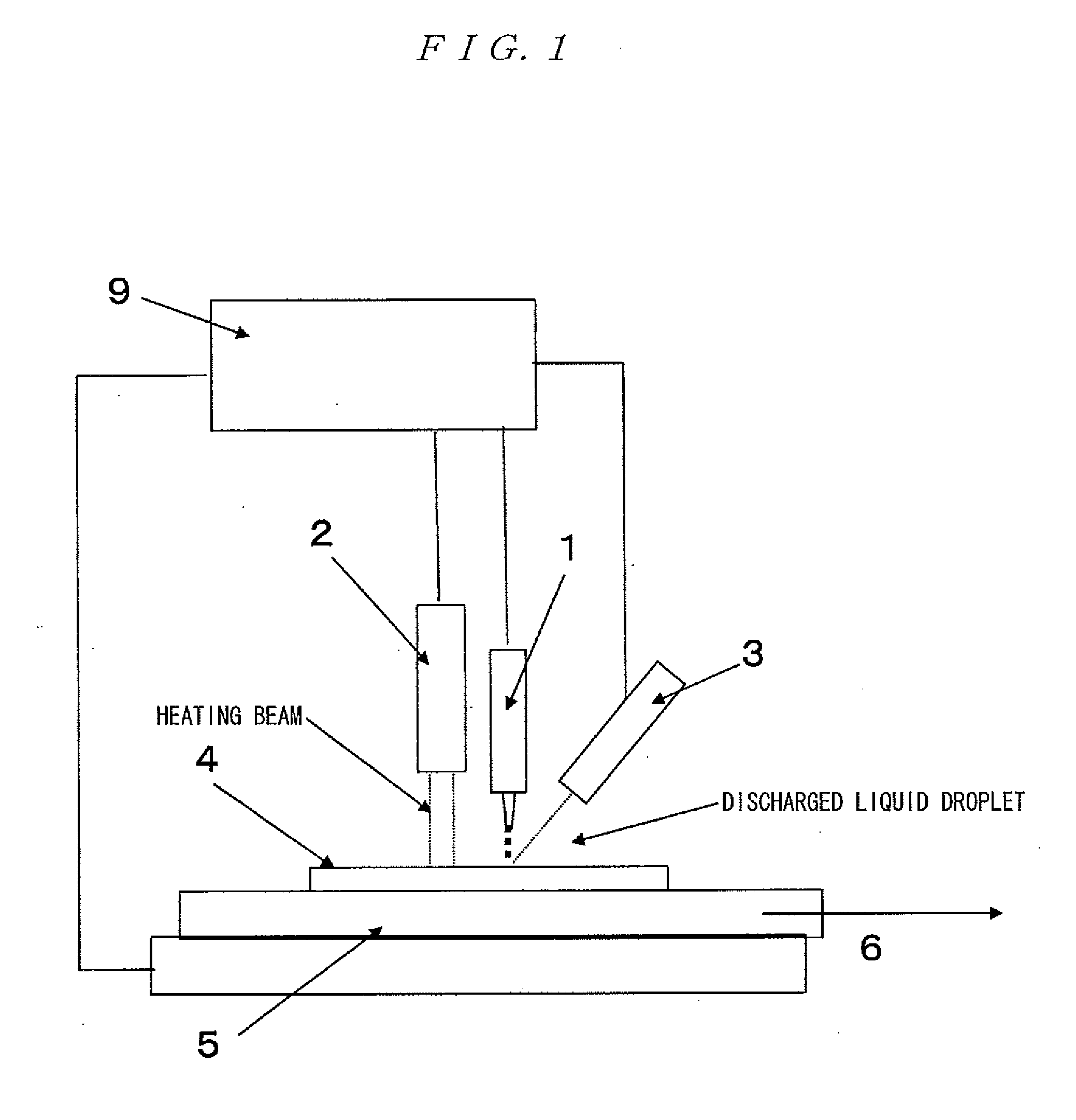
[0052]In the present invention, to form a thick fine pattern, when the liquid droplet diameter is too small, the material supply amount itself is reduced, and hence the drawing needs to be repeated at the same place to obtain a thick fine pattern. However, when the liquid droplet diameter is set in the range of 10 μm to 150 μm, more preferably in the range of 50 μm to 100 μm, a fine pattern having a thickness of 0.5 μm or more and having a line shape can be formed without repetition of the drawing.

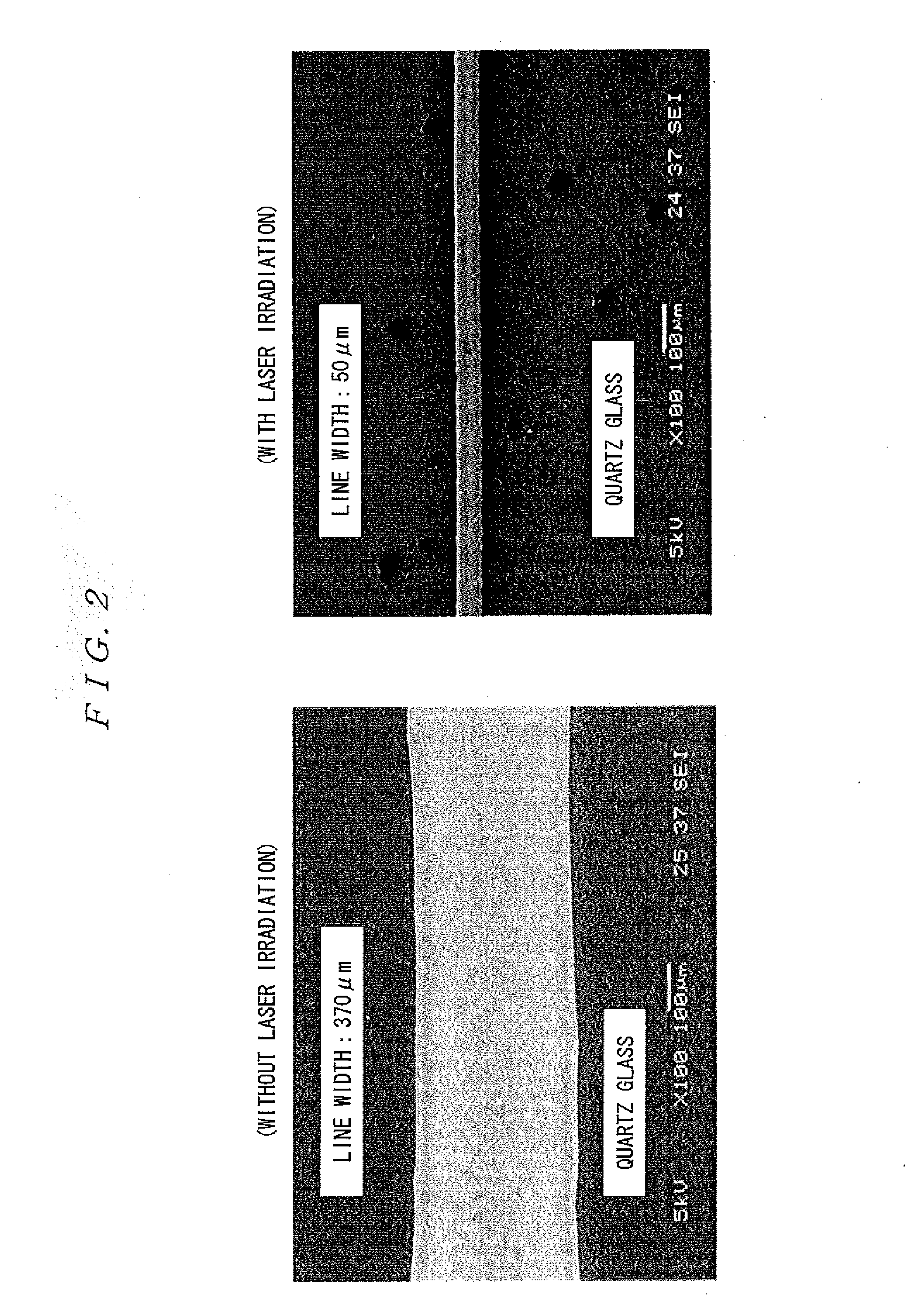
[0053]Further, when the heating temperature of the substrate by the laser irradiation or the lamp heating is too high, a boiling phenomenon is caused due to local unevenness in the heating of the liquid droplets impacted on the substrate, so that a delicate and smooth fine pattern surface cannot be obtained. Further, when the heating temperature of the substrate is too low, the drying effect is insufficient, so that the liquid droplet spreads. The boiling phenomenon and the insufficient dr...


PUM

PropertyMeasurementUnit
aspect ratioaaaaaaaaaa
acute angleaaaaaaaaaa
widthaaaaaaaaaa

Abstract

Disclosed herein is a fine and thick wiring drawn at high speed in such a manner that a region on the substrate, on which region the liquid droplet is scheduled to impact, is heated beforehand, and that immediately after the impact of the liquid droplet on the substrate, the liquid droplet is promptly solidified so as thereby to suppress the spread of the liquid droplet due to the wettability of the liquid droplet to the substrate, and also to suppress the clogging of the nozzle due to the heating of the substrate. Thereby, even in the case where a liquid droplet having a larger volume than before is used, high-speed drawing of a thick and fine wiring having a line width approximately equal to the liquid droplet size is realized independently of the substrate material.

Description

TECHNICAL FIELD[0001]The present invention relates to a pattern drawing method, a pattern drawing apparatus, and a wiring pattern, and relates to, for example, a thin film forming method, a device manufacturing method, an electro-optical apparatus manufacturing method, and an electronic device.BACKGROUND ART[0002]A highly functional component requires design and manufacturing techniques which can cope not only with the size and cost reduction of the product but also with the product diversification and the reduction in product cycle time. Also, in the MEMS technique which provides highly functional components and which is expected as a driving force of new industry, techniques for higher integration and higher functionality have been required. At the same time, in the stage of practical application, it has also become important to solve problems, such as reduction in the manufacturing cost and production time in a small amount and many kinds of products.[0003]Further, in order to pr...

Claims


Application Information

Patent Timeline
Patent Type & Authority Applications(United States)
IPC IPC(8): B41J2/04
CPCH05K3/1208H05K3/125H05K2203/013H05K2203/107H05K2203/1105H05K2203/111
Inventor AKEDO, JUNENDO, AKITO
Owner NAT INST OF ADVANCED IND SCI & TECH
Why Eureka
Try Eureka