Method and circuit for providing RF isolation of a power source and an RF device employing such a circuit

a technology of rf isolation and power source, which is applied in the direction of transmission, line-transmission details, instruments, etc., can solve the problems affecting the rf section of the device, and methods may not be effective, so as to eliminate or reduce the effect of low battery impedance and the minimum space required

Inactive Publication Date: 2008-07-24
POWERID LTD
View PDF20 Cites 18 Cited by
  • Summary
  • Abstract
  • Description
  • Claims
  • Application Information

AI Technical Summary

Benefits of technology

[0006]Embodiments of the present invention provide a battery operated RF device which includes an isolation circuit to isolate the effect of battery impedance or the battery metallic parts from the RF section of the device. In some embodiments, the isolation circuit comprises a quarter wavelength section or multiple quarter wavelength sections of transmission line at the device operating frequency. A quarter wavelength section of transmission line is effective over a relatively wide frequency band, such as for example f(quarter wavelength)±7.5%. The quarter wavelength transmission line section may be constructed in any suitable configuration, size or shape. In some embodiments the quarter wavelength section may be an open quarter wavelength transmi

Problems solved by technology

A problem associated with RF devices which include an RF section and a power source, is that the battery impedance and/or battery metallic parts may affect the RF section of the device.
Ho

Method used


Image

  • Method and circuit for providing RF isolation of a power source and an RF device employing such a circuit
  • Method and circuit for providing RF isolation of a power source and an RF device employing such a circuit
  • Method and circuit for providing RF isolation of a power source and an RF device employing such a circuit

Examples


Embodiment Construction

[0013]In the following description of different embodiments of the invention, identical reference numerals will be used to refer to identical components or to components that fulfill a common function.

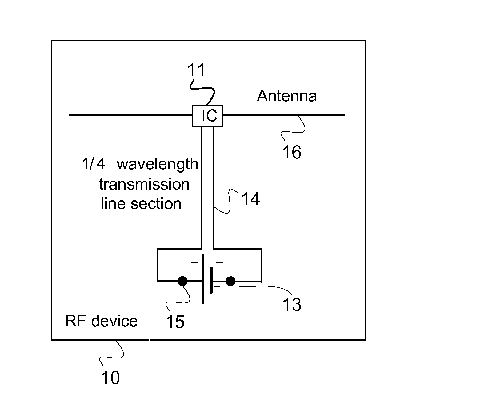
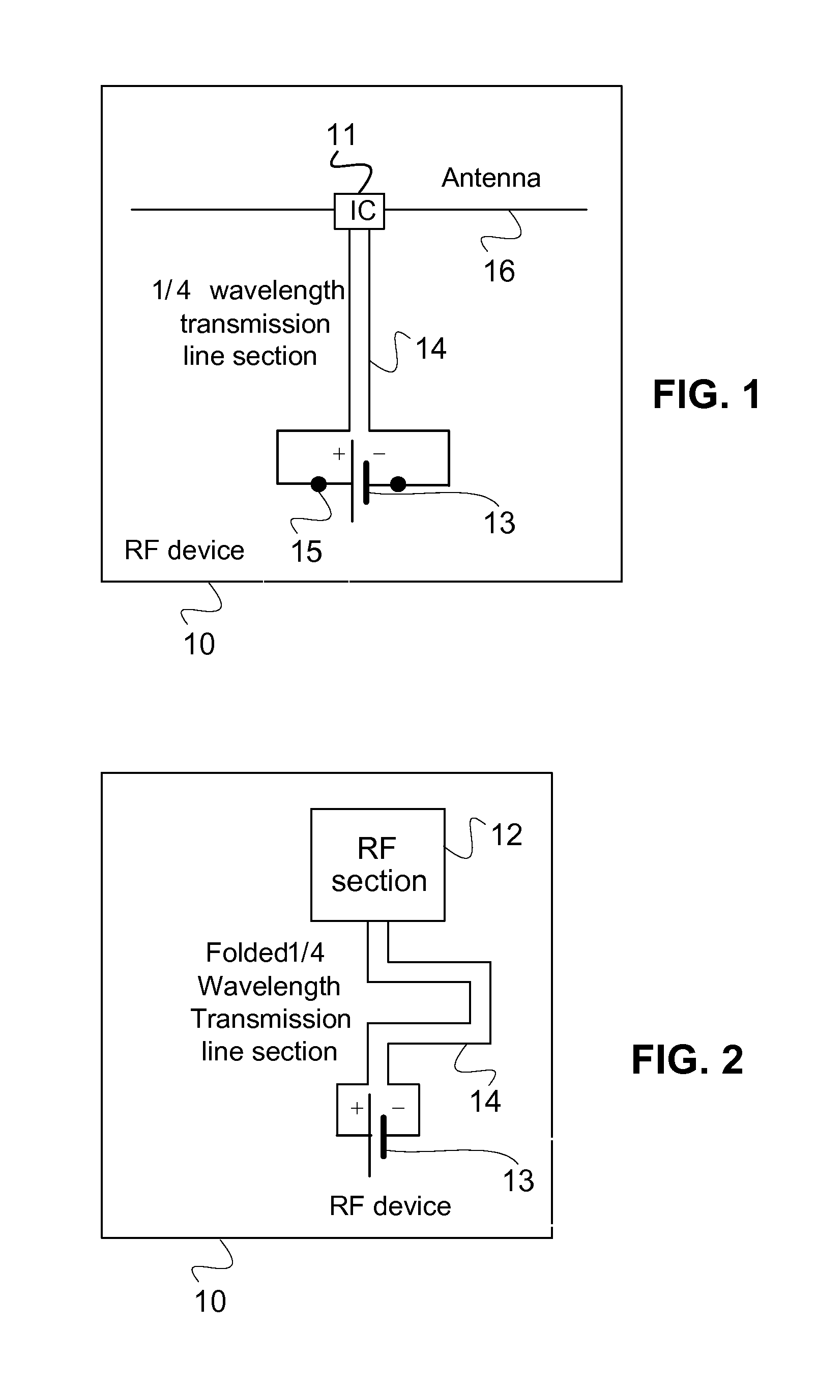
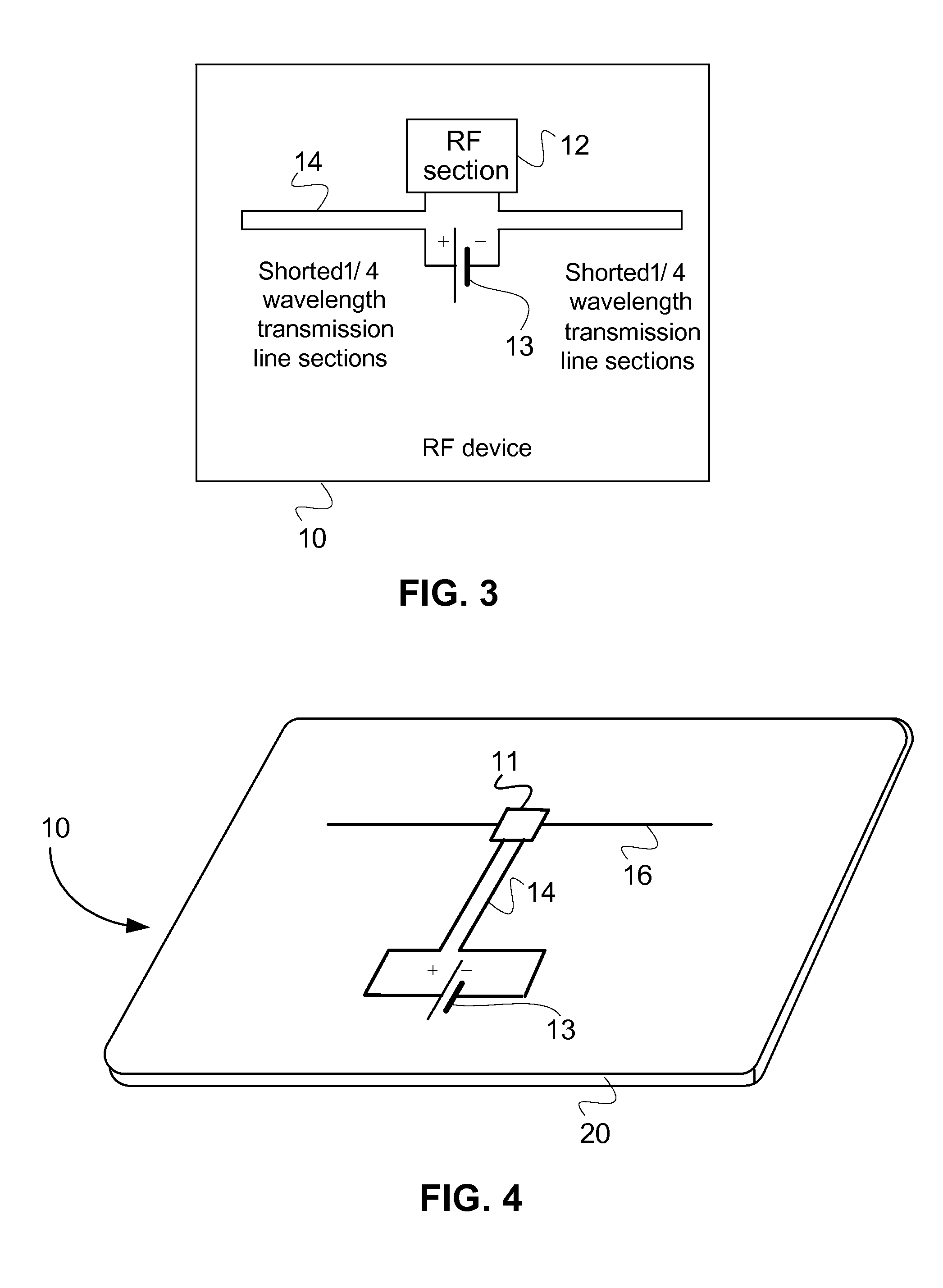
[0014]FIG. 1 shows a schematic representation of a device 10 according to one embodiment of the present invention. As can be seen from FIG. 1, the device includes electronic circuitry 11, such as an integrated circuit which includes a RF section 12 (shown in FIG. 2), at least one power source which may include a battery 13 and an isolation circuit 14 to RF isolate the at least one power source. Optionally, the power source 13 may be removably coupled to the isolation circuit 14 by respective power connectors 15. In some embodiments, device may include an antenna 16.

[0015]The isolation circuit 14 that is used to RF isolate the power source 13 may include an open quarter wavelength transmission line section. Examples of quarter wavelength transmission line section include, but are not li...


PUM


Abstract

A radio frequency (RF) device includes electronic circuitry having a radio frequency section and power connectors for electrically connecting the electronic circuitry to at least one power source for providing the device with power. At least one quarter wavelength transmission line is connected between the power connectors and the electronic circuitry and acts as a low-to-high impedance transformer at RF, while at low frequencies i.e. DC, it provides a physical connection. Thus, the transmission line section has substantially no effect on the DC connection between the power source and the device.

Description

CROSS REFERENCE TO RELATED APPLICATION[0001]The present application claims the benefit of U.S. Provisional Patent Application No. 60 / 829,780, filed on Oct. 17, 2006, the disclosure of which is hereby incorporated by reference.FIELD OF THE INVENTION[0002]The present invention relates in general to an RF device, and in particular to battery operated RF devices.BACKGROUND OF THE INVENTION[0003]There are many examples of battery operated radio frequency (RF) devices, such as RF Short Range Devices (SRD), RF Automatic Meter Reading (AMR) devices, active RFID devices and battery assisted passive RFID devices. A problem associated with RF devices which include an RF section and a power source, is that the battery impedance and / or battery metallic parts may affect the RF section of the device. This is especially so when the device includes a larger battery. As such, it is desirable to isolate the effect of the battery impedance and / or the battery metallic parts from the RF section of the de...

Claims


Application Information

Patent Timeline
IPC IPC(8): H04B3/28
CPCG06K19/07749H01Q1/52H01Q1/2225
Inventor NITZAN, ZVILAVEE, DORONALMOG, BENYAMIN
Owner POWERID LTD
Why Eureka
Try Eureka