Image Processing Device

a processing device and image technology, applied in the field of image processing devices, can solve the problems of difficult use of the techniques in documents 1 to 8, blind image deconvolution/restoration, and general ill-posed problems of deblurring

Inactive Publication Date: 2008-07-24
KK TOSHIBA
View PDF13 Cites 80 Cited by
  • Summary
  • Abstract
  • Description
  • Claims
  • Application Information

AI Technical Summary

Problems solved by technology

This problem is called blind image deconvolution/restoration.
Even if the PSF is available or is known in advance, deblurring is generally an ill-posed problem.
Deblurring tends to amplify noise.
If none of the conditions (1) to (4) are satisfied, using of the techniques in Documents 1 to 8 is difficult.
However, if blur variation in the image data is large, for example, if the amount of blur varies among a plurality of subjects with arbitrary shapes in the im

Method used


Image

  • Image Processing Device
  • Image Processing Device
  • Image Processing Device

Examples


first embodiment

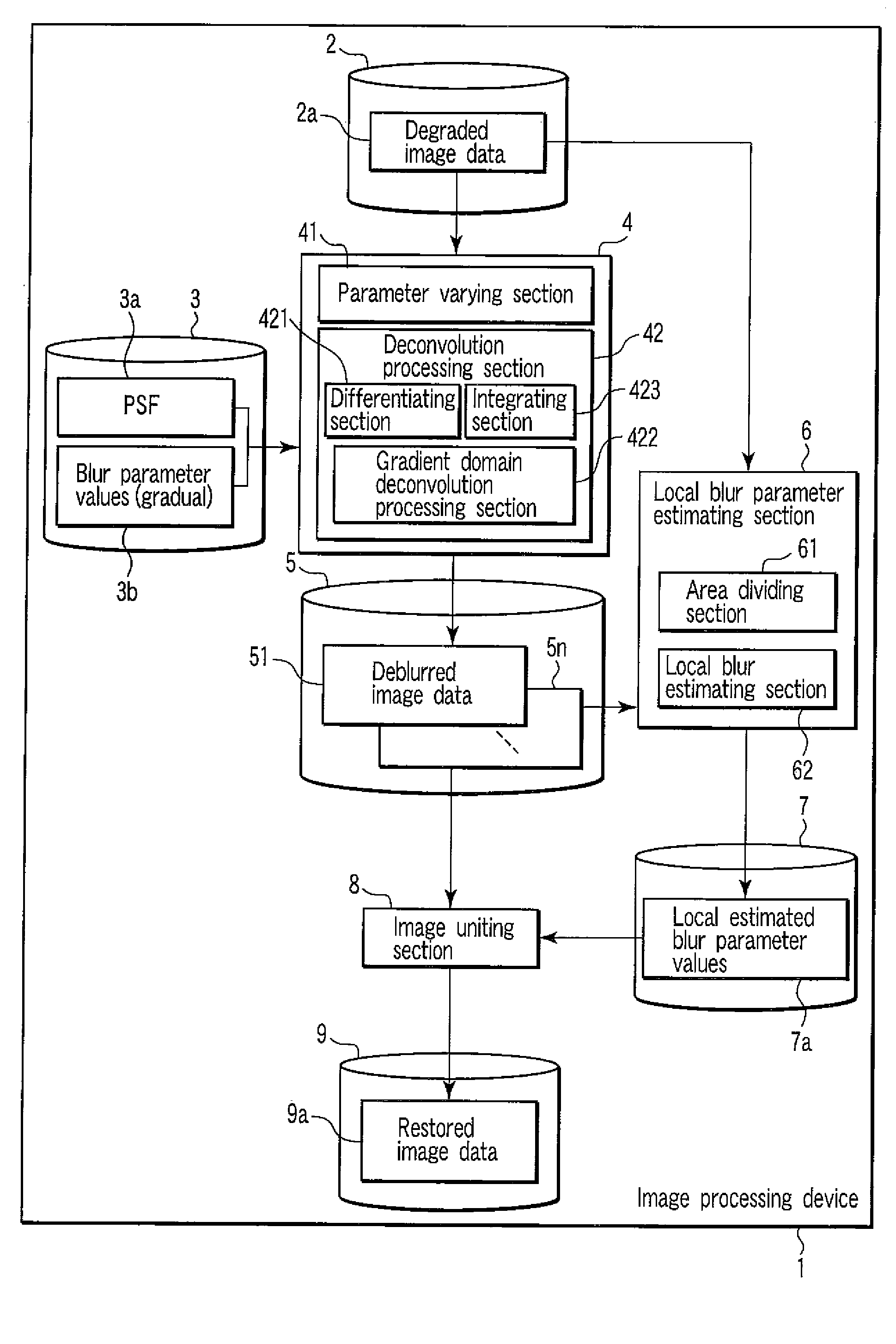
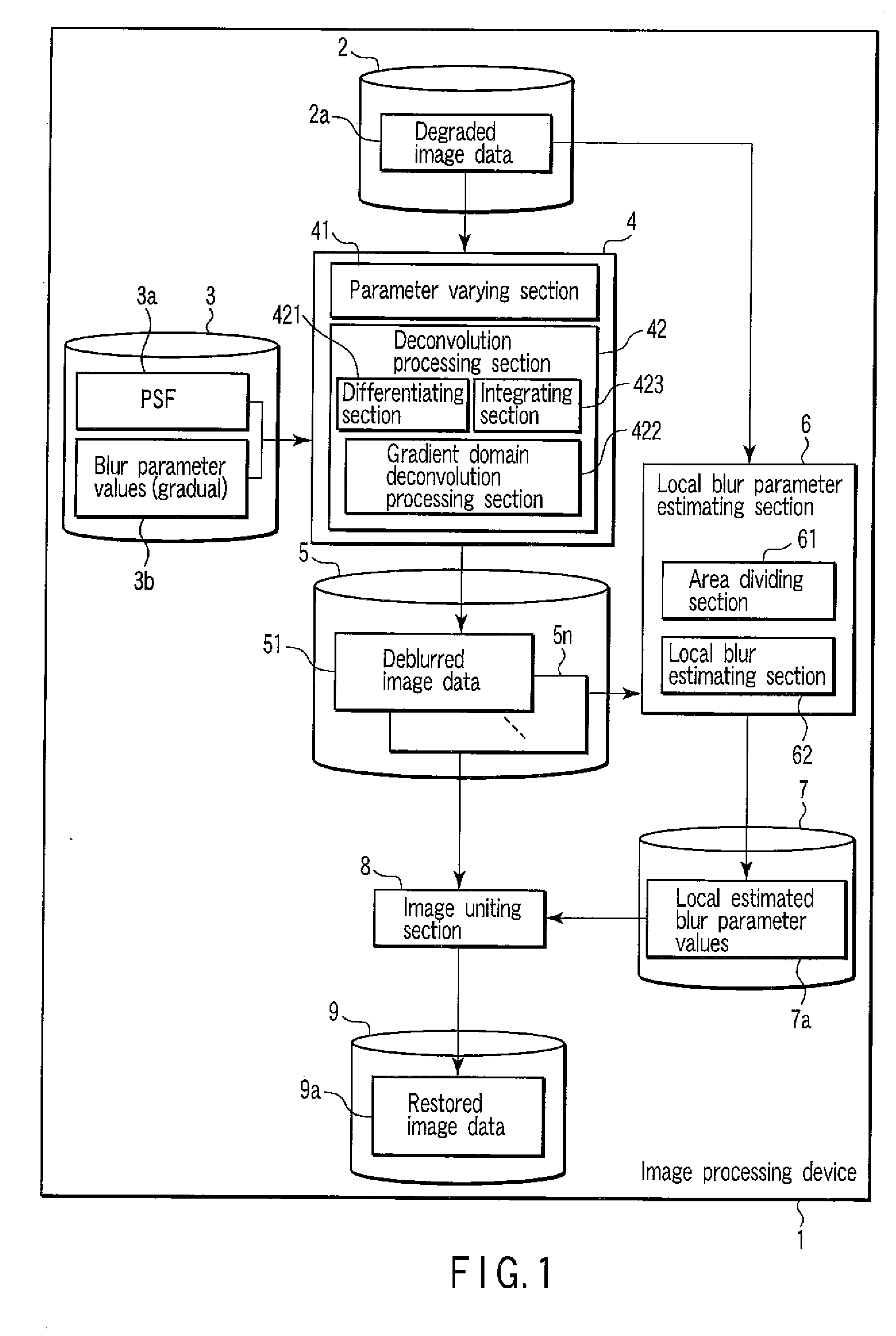
[0036]An image processing device in accordance with the present embodiment deblurs image data.

[0037]The image processing device in accordance with the present embodiment performs different deblurring operations for the input image data, divides the image data into appropriate areas in accordance with an image content of the image data, performs a local blur estimation for each area, and unites the appropriately deblurred image data for each area. Thus, even if a state of a blur within single image data is not uniform, particularly, even if a variation of the blur state within the single image data is large, the image processing device can generate varied image data with a different blur state, at a high speed, while preventing possible noise amplification.

[0038]FIG. 1 is a block diagram showing an example of the image processing device in accordance with the present embodiment. In the present embodiment, input image data is degraded image data 2a and output image data is restored im...

second embodiment

[0147]In the present embodiment, description will be given of an example of application of the image processing device in accordance with the first embodiment.

Example of Application of the Image Processing Device

[0148]FIG. 12 is a block diagram showing a first example of application of the image processing device 1 in accordance with the present invention.

[0149]FIG. 12 shows an example in which image data taken with an imaging device 12 is converted.

[0150]A light (for example, sunlight or room light) emitted by a light source 13 impinges on a subject (for example, a person, an object, or a scenery) 14. Reflected light from the subject 14 is received by the imaging device 12 via a lens 15. The size and refractive index of the lens 15 are determined in accordance with the application. For example, CCD or a CMOS sensor is used as the imaging device 12.

[0151]The imaging device 12 outputs an electric signal corresponding to the quantity of received light to a digitizer 16. The digitizer ...


PUM


Abstract

An image processing device according to an example of the invention comprises a differentiating section which differentiates input image data to generate gradient image data, a gradient domain deconvolution processing section which applies a deconvolution to the gradient image data, the deconvolution performing deblurring corresponding to a prior distribution of an image gradient of an image to generate deconvolved data, and an integrating section which integrates the deconvolved data to generate deblurred image data.

Description

CROSS-REFERENCE TO RELATED APPLICATIONS[0001]This application is based upon and claims the benefit of priority from prior Japanese Patent Application No. 2007-011878, filed Jan. 22, 2007, the entire contents of which are incorporated herein by reference.BACKGROUND OF THE INVENTION[0002]1. Field of the Invention[0003]The present invention relates to an image processing device which converts a blur state within an image.[0004]2. Description of the Related Art[0005]A general method of restoring degraded image data is assumed to be executed in a circumstance that satisfies at least one of the following conditions (1) to (4).[0006](1) A point-spread function (PSF) of input degraded image data is uniform (for example, Document 1: U.S. Pat. No. 6,859,564, Document 2: U.S. Pat. No. 5,561,611, and Document 3: U.S. Pat. No. 6,154,574).[0007](2) The PSF for the degraded image data is not uniform but varies slowly (for example, Document 4: M. K. Ozkan, A. M. Tekalp, and M. I. Sezan. Identificat...

Claims


Application Information

Patent Timeline
IPC IPC(8): G06K9/40
CPCG06T5/003
Inventor BANDO, YOSUKENISHIDA, TOMOYUKI
Owner KK TOSHIBA
Why Eureka
Try Eureka