
Camera and strobe device

a strobe light and camera technology, applied in the field of camera and strobe light, can solve the problems of inability to finely set color temperature, inability to match the color temperature of the subject field, and increase the area of useless data based on the high color temperature, so as to achieve efficient utilization of memory

Active Publication Date: 2008-07-24
FUJIFILM CORP
View PDF3 Cites 28 Cited by
  • Summary
  • Abstract
  • Description
  • Claims
  • Application Information

AI Technical Summary

Benefits of technology

[0015]The present invention has been made in view of the above described circumstances, and it is an object of the present invention to provide a camera which can ensure strobe shooting with strobe light at a color temperature which is approximately same as a color temperature of a subject field even if there is any error in measurement, setting or the like of the color temperature of the subject field. Furthermore, it is another object of the present invention to provide a strobe device and a camera which can minimize required data of a ratio of light emission amounts of R, G and B, and can efficiently utilize a memory.
[0041]According to the present invention, even in a situation where the strobe light emission at a right color temperature is difficult, it is possible to perform the shooting with the strobe light emission at the color temperature intended by the shooter because in a color bracketing shooting, shootings are performed in conjunction with continuously emitting the strobe light at the different color temperature. Furthermore, it is possible to provide the strobe device and the camera which can minimize required data of the ratio of the light emission amounts of R, G and B for varying a color temperature of an emitted light color of a strobe in which the light emitting elements of R, G and B are used, and can utilize the memory efficiently.

Problems solved by technology

Moreover, in the invention according to Japanese Patent Application Laid-Open No. 2002-116481, if there is any error in measurement of a color temperature of a subject field, there is a problem that the color temperature of the strobe light which has been set based on a result of the measurement cannot match the color temperature of the subject field.
However, even with the same color temperature difference, the colors significantly vary in an area of a low color temperature, while the colors insignificantly vary in an area of a high color temperature.
Therefore, if RGB ratio data is held at regular intervals of the color temperature, there is a problem in which the color temperature cannot be finely set in the area of the low color temperature if the intervals of the color temperature are wide, and useless data increases in the area of the high color temperature if the intervals of the color temperature are narrow.

Method used


Image

  • Camera and strobe device
  • Camera and strobe device
  • Camera and strobe device

Examples


first embodiment

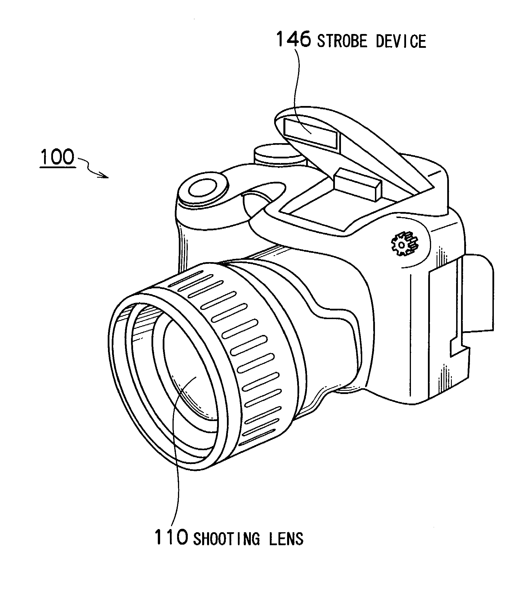
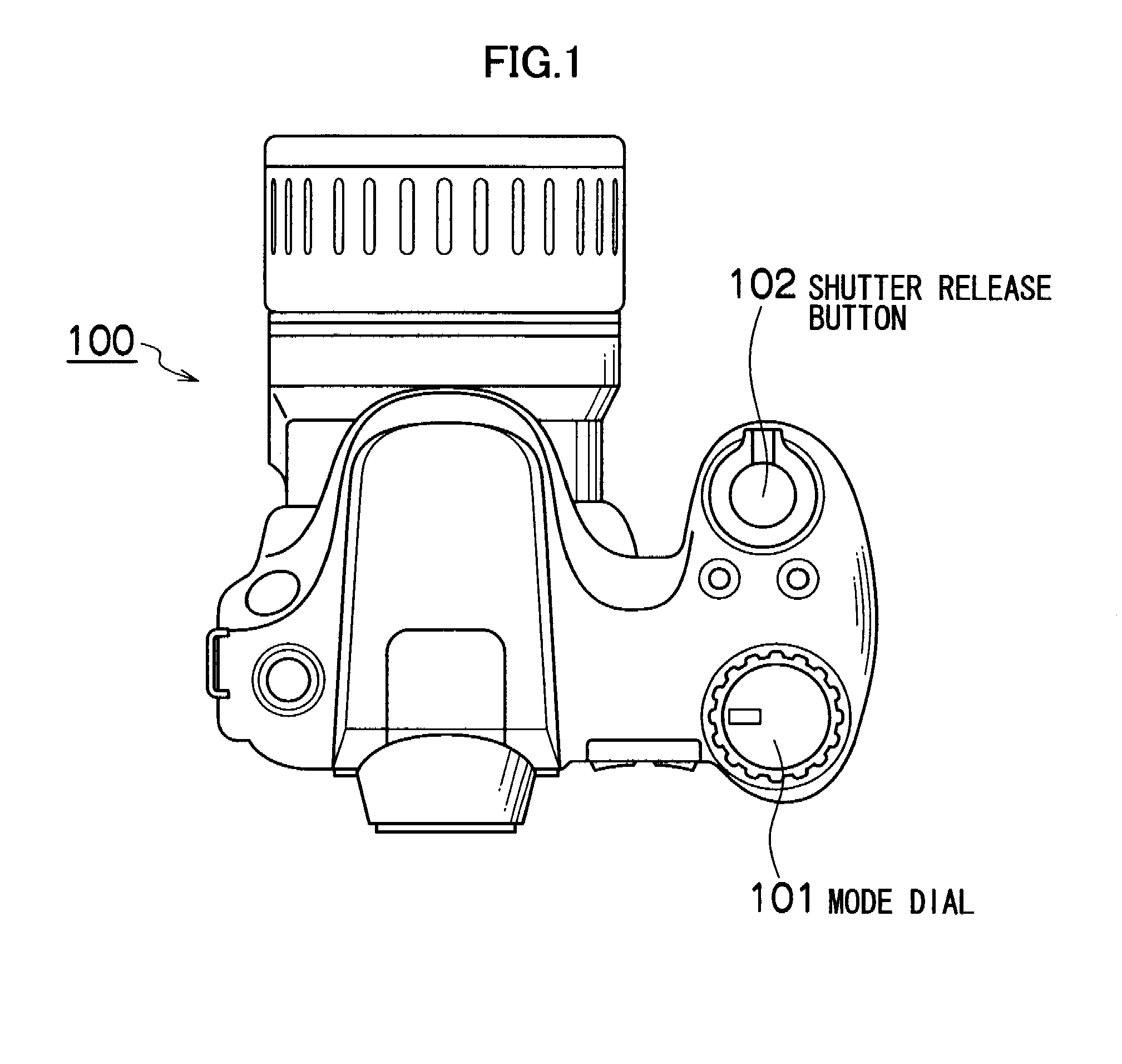
[0059]FIG. 1 is a top view of an electronic camera capable of color bracketing shooting according to an embodiment of the present invention.

[0060]As shown in FIG. 1, a mode dial 101 can be rotated to set to any shooting mode among a manual shooting mode, an auto shooting mode, a person mode and the like. Moreover, in front of the mode dial 101, a shutter release button 102 having a switch S1 to be turned on for half-pressing the button and a switch S2 to be turned on for fully pressing the button are provided.

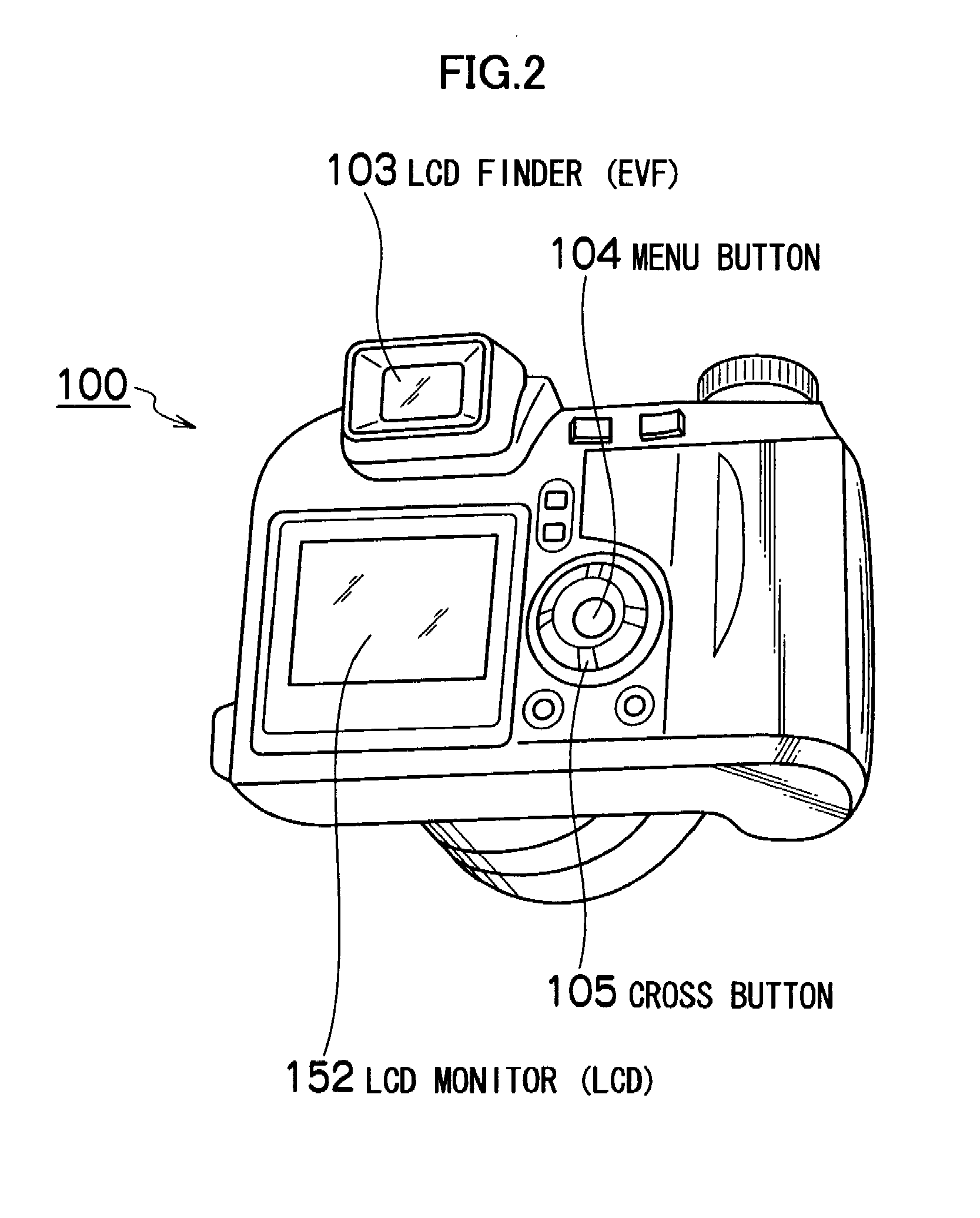
[0061]FIG. 2 is a rear perspective view of the electronic camera capable of the color bracketing shooting according to the embodiment of the present invention.

[0062]On a rear side of this electronic camera 100, as shown in FIG. 2, an LCD finder 103, a menu button 104, a cross button 105 and an LCD monitor 152 are provided.

[0063]FIG. 3 is a front perspective view of the electronic camera capable of the color bracketing shooting according to the embodiment of the present inventio...

second embodiment

[0157]As a second embodiment related to the present invention, a camera not including a dedicated display related to the color temperature such as the color temperature measurement completion display lamp 201 or the color temperature set value mark 202 will be described.

[0158]FIGS. 14A and 14B are displays in the LCD finder 103 of the camera not including the dedicated display related to the color temperature of the second embodiment related to the present invention.

[0159]A frame for a focus is displayed in the LCD finder 103. FIG. 14A is the display at a normal time and FIG. 14B is the display when the subject is in focus.

[0160]Here, the case of setting the color temperature selection for the color bracketing shooting to “M” (S12 in FIG. 8) will be described.

[0161]In the camera of the second embodiment related to the present invention, the frame for the focus in the LCD finder 103 is also used for the display of the matching of the color temperature of the subject field and the set...

third embodiment

[0168]The camera of a third embodiment related to the present invention will be described by using FIGS. 15 and 16.

[0169]FIG. 15 is a flowchart representing operations of the camera of the third embodiment related to the present invention, and FIG. 16 is a display screen on the LCD monitor 152 of the camera of the third embodiment according to the present invention.

[0170]In the camera 100 of the third embodiment related to the present invention shown in FIG. 1, the mode dial 101 can be rotated to set to any shooting mode among the manual shooting mode, the auto shooting mode and a shooting scene selection mode.

[0171]When the mode dial 101 is set to the shooting scene selection mode (S31 in FIG. 15), a shooting scene selection screen shown in FIG. 16 is displayed on the LCD monitor 152.

[0172]A shooting scene can be selected among a person mode, a landscape mode, a sport mode, a night scene mode, an evening scene mode and a beach mode, and the cursor is moved up and down with the cros...


PUM


Abstract

A camera which continuously performs shooting at predetermined time intervals in conjunction with one shutter release operation, comprises: a strobe light source which emits strobe light whose color temperature is adjustable; a light emission control device which controls the strobe light source to emit the strobe light in synchronization with each shooting in the continuous shooting; and a color temperature adjustment device which adjusts the color temperature of the strobe light emitted from the strobe light source for each shooting in the continuous shooting to vary color temperature with each shooting within a predetermined color temperature variable range which has been previously set. Thereby, even in a situation where the strobe light emission at a right color temperature is difficult, it is possible to perform the shooting with the strobe light emission at the color temperature intended by the shooter.

Description

BACKGROUND OF THE INVENTION[0001]1. Field of the Invention[0002]The present invention relates to a camera and a strobe device, and more particularly, to a camera and a strobe device which can vary a color temperature of an emitted light color of strobe light.[0003]2. Description of the Related Art[0004]A camera provided with an auto bracketing shooting function has been widely known in which multiple photos are continuously and automatically shot only with one release operation while the exposure value is varied stepwise, with respect to a determined exposure value of the camera, that is, shutter speed and an aperture value.[0005]Japanese Patent Application Laid-Open No. 5-196985 describes a technique capable of quickly and accurately performing the auto bracketing shooting even if the auto bracketing shooting is performed by using a strobe device.[0006]Moreover, among cameras such as digital still cameras, there is also a camera provided with a white balance bracketing shooting fun...

Claims


Application Information

Patent Timeline
IPC IPC(8): G03B15/03G03B15/02
CPCG03B15/03
Inventor KAWAKAMI, CHIKUNI
Owner FUJIFILM CORP
Learn More