Fastener with stepped head for composite decking

Inactive Publication Date: 2008-07-24
SIMPSON STRONG TIE
View PDF20 Cites 1 Cited by
  • Summary
  • Abstract
  • Description
  • Claims
  • Application Information

AI Technical Summary

Benefits of technology

[0008]To at least partially overcome these disadvantages of previously known devices, the present invention provides a fastener

Problems solved by technology

Such composite lumber products have a disadvantage referred to as “flagging” created by the use of screws and other fasteners to secure the composite lumber products as, for example, to underlying wooden joists in a decking application.
It is some

Method used


Image

  • Fastener with stepped head for composite decking
  • Fastener with stepped head for composite decking
  • Fastener with stepped head for composite decking

Examples


Example

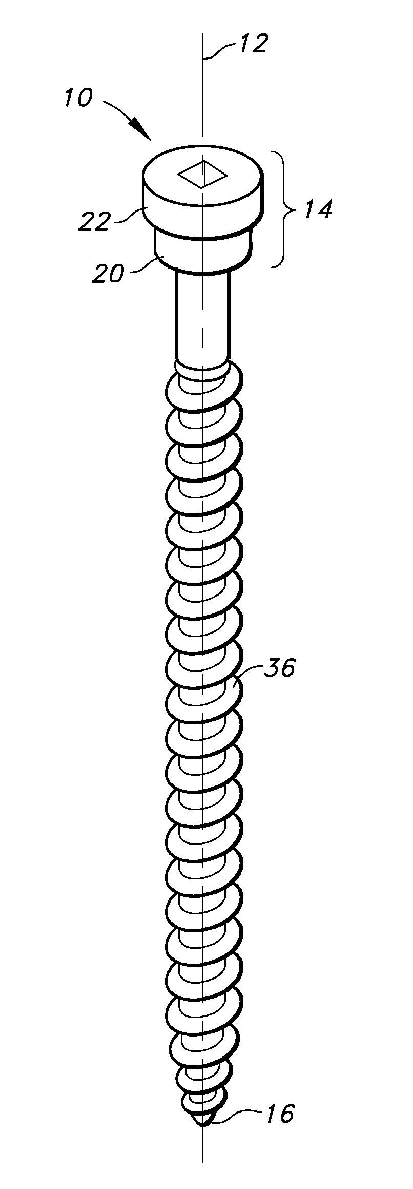
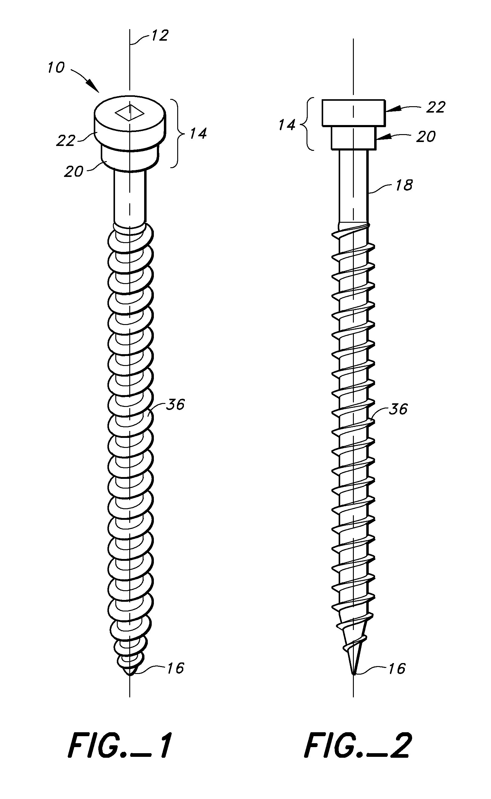
[0037]Reference is made first to FIG. 1 which shows as a first embodiment of the invention a screw 10 which is disposed about a longitudinal axis 12 and has a head 14 at an upper end, a tip 16 at a lower end and a shank 18 extending from the head 14 to the tip 16 about the axis 12. As best can be seen in the end cross-section of FIG. 4, in any cross-section normal to the axis 12 at any respective position along the axis, the head 14 is circular about the axis and has a respective radius.

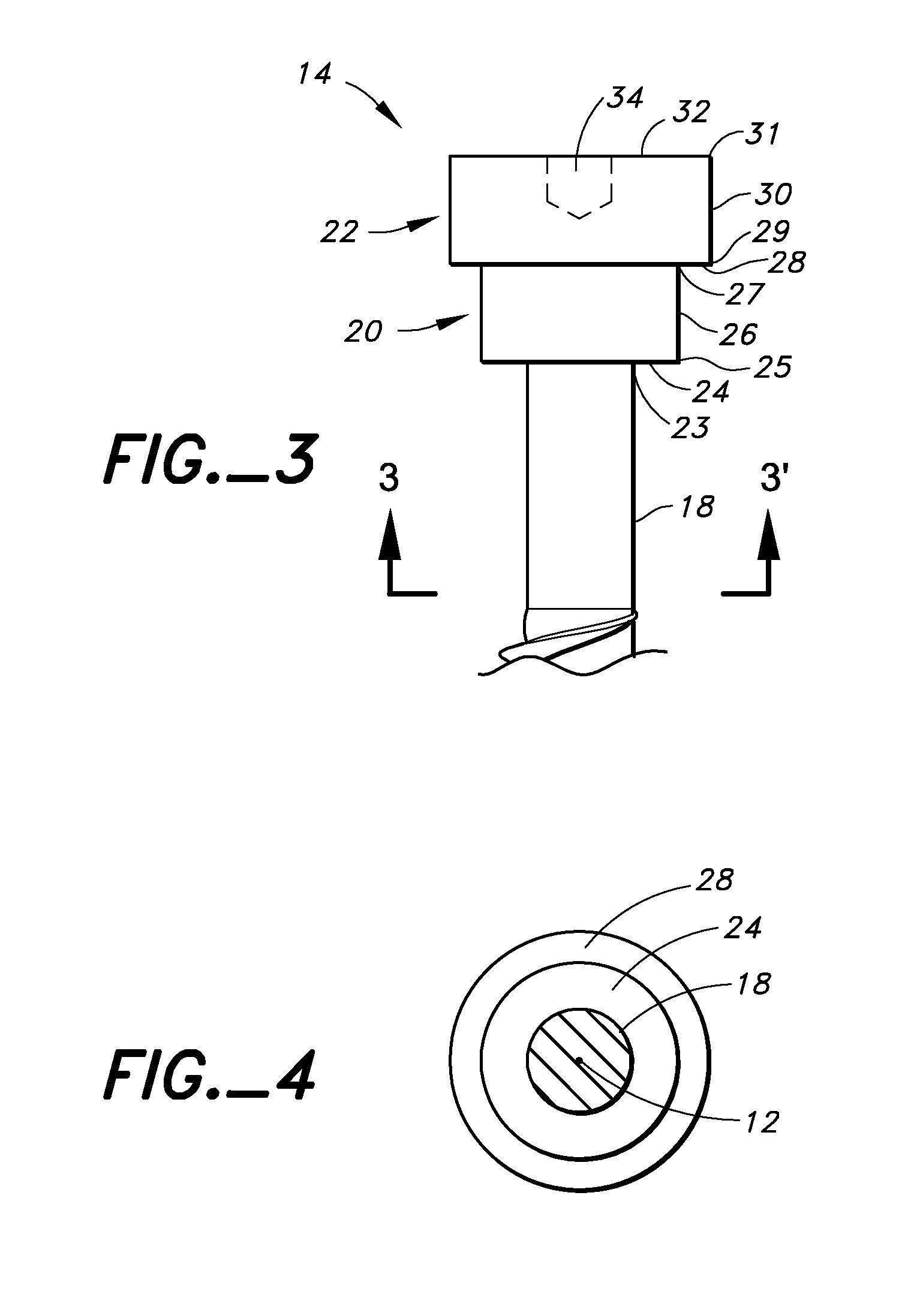
[0038]As may be seen, the radius of the head is reduced in a stepped manner towards the tip 16. In this regard, the head 14 may be considered to comprise a first disc portion 20 and a second disc portion 22, each being cylindrical and disposed coaxially about the axis 12 normal to the axis. The first disc portion 20 is disposed below the second disc portion 22 and joins the second disc portion 22 to the shank 18.

[0039]The first disc portion provides a first shoulder surface 24 and a first side wall 2...

Example

[0045]Reference is made to FIGS. 6 to 8 which illustrate a second embodiment of a screw 10 in accordance with the present invention. The screw 10 of FIG. 6 differs from the screw 10 of FIGS. 1 to 4 insofar as a third cylindrical disc portion 44 is provided of a radius greater than the radius of the second disc portion 28. The third disc portion has a third shoulder surface 46 and a third side wall 48 with a lower edge 47 and an upper edge 49. The second side wall 30 merges into the third shoulder surface 46 at the upper edge 31 of the second side surface. The third shoulder surface 46 merges into the third side wall 48 at the lower edge 47 of the third side wall. The third side wall merges at its upper end 49 into a top surface 32 of the screw. In the embodiment illustrated in FIG. 5, three shoulder surfaces are provided which, on driving a screw downwardly into a workpiece, each engage material of the workpiece and tend to draw the material of the workpiece downwardly.

[0046]FIG. 6 ...


PUM

PropertyMeasurementUnit
Angleaaaaaaaaaa

Abstract

A fastener with a head having a stepped configuration in assist in drawing down a composite material about a fastener to reduce flagging.

Description

SCOPE OF THE INVENTION[0001]This invention relates to fasteners and, more particularly, for fasteners to secure composite lumber product.BACKGROUND OF THE INVENTION[0002]Composite wood is known and has been used, for example, as a substitute for wood in areas where wood can deteriorate quickly due to environmental conditions.[0003]Composite wood products typically comprise mixtures of fibers such as waste wood fiber and plastic material preferably recycled plastic material. Such polymer-fiber composites are also known as synthetic wood, composite lumber, wood-polymer lumber and similar such names.[0004]Such composite lumber and its methods of manufacture described, for example, in U.S. Pat. No. 6,344,268 to Stucky et al, issued Feb. 5, 2002; U.S. Pat. No. 5,759,680 to Brooks et al, issued Jun. 2, 1998 and U.S. Pat. No. 5,088,910 to Goforth et al, issued Feb. 18, 1992.[0005]Such composite lumber is commercially available. One such product is manufactured under the trade mark TREX, by...

Claims


Application Information

Patent Timeline
IPC IPC(8): F16B23/00F16B5/02F16B25/10F16B35/04
CPCF16B5/0275F16B25/0015F16B35/048F16B25/0063F16B25/10F16B25/0057
Inventor HABERMEHL, G. LYLE
Owner SIMPSON STRONG TIE
Why Eureka
Try Eureka