Suction roller for transporting flat material blanks

a flat material and suction roller technology, applied in the direction of applications, instruments, roads, etc., can solve the problems of insufficient order of magnitude, undesirable effort and expenditure in material, cost, storage, etc., and achieve the effect of great suction cross-section

Inactive Publication Date: 2008-07-24
WINKLER DUNNEBIER GMBH
View PDF22 Cites 15 Cited by
  • Summary
  • Abstract
  • Description
  • Claims
  • Application Information

AI Technical Summary

Benefits of technology

[0014]The suction slits that open into the mantle surface can be covered, according to the invention, using a slit cover disposed on the mantle surface in releasable or non-releasable manner. The slit cover covers the suction slits in such a way that a suction air connection between the suction slits and the surroundings becomes possible only by the passage holes provided in the slit cover, which holes align at least partially with the suction slits. Because at least suction slits that are adjacent to one another in the circumferential direction can have suction air applied to them independent of one another, a fine raster of suction holes, i.e. rows of suction holes that can have suction air applied to them independent of one another is created, which allows the transport of flat material blanks having the most varied formats. With regard to the distribution, in terms of area, of suction holes or rows of suction holes that can be controlled independent of another, the triggering is refined, as compared with the state of the art, in such a manner that any desired formats can be transported using the suction roller according to the invention, and corresponding rows of blanks can be separated. In particular, among other things, an advantage that is particularly important in the case of relatively small flat material pieces is achieved, namely that the flat material pieces having various formats can always be held directly at their front edge, without having to replace the suction roller or having to make other changes on it. In this connection, it should be pointed out that the suction slits are preferably disposed so as to be uniformly spaced and distributed over the entire circumference of the suction roller according to the invention.
[0015]In the case of a change in format, suction holes at whose position no suction effect is desired, as a function of the format, can be closed off by simply being glued shut. If the slit cover provided with the passage holes is disposed so as to be releasable from the mantle surface, slit covers for formats that are to be produced more frequently may be kept on hand. Such slit covers have passage holes only at certain locations as a function of the format. In the case of the formats in question, it will then not be necessary to glue shut any holes, which is an advantage, whereby the advantage that no format-dependent complete suction roller has to be produced continues to be maintained.
[0016]Preferably, each suction slit has suction air applied to it through an axial channel, which is disposed in one of the faces of the suction roller and opens into the suction slit, in each instance. It is particularly advantageous to dispose those axial channels that are assigned to two or more adjacent suction slits at different radial distances from the roller axis, i.e. at different radial depths, proceeding from the mantle surface. In this manner, there is the possibility of selecting the suction cross-section of the axial channels to be relatively great, despite the smallest possible distance of the suction slits from one another, according to the invention, for example as great as it has already been selected in the case of the suction rollers known from the state of the art. In this way, spatial interpenetration of the different axial channels having a great suction cross-section is avoided, according to the invention. At the same time, it is guaranteed, in advantageous manner, that the suction volume required for producing the desired suction effect can be drawn in.

Problems solved by technology

This order of magnitude is not sufficient, in practice, to make controllable suction air bores available that lie so close to one another that the same suction roller can always be used as a blank separation roller, independent of the label format.
This requirement leads to undesirable effort and expenditure in terms of costs, material, and storage.

Method used


Image

  • Suction roller for transporting flat material blanks
  • Suction roller for transporting flat material blanks
  • Suction roller for transporting flat material blanks

Examples


Embodiment Construction

[0019]Other objects and features of the present invention will become apparent from the following detailed description considered in connection with the accompanying drawings. It should be understood, however, that the drawings are designed for the purpose of illustration only and not as a definition of the limits of the invention.

[0020]In the drawings, wherein similar reference characters denote similar elements throughout the several views:

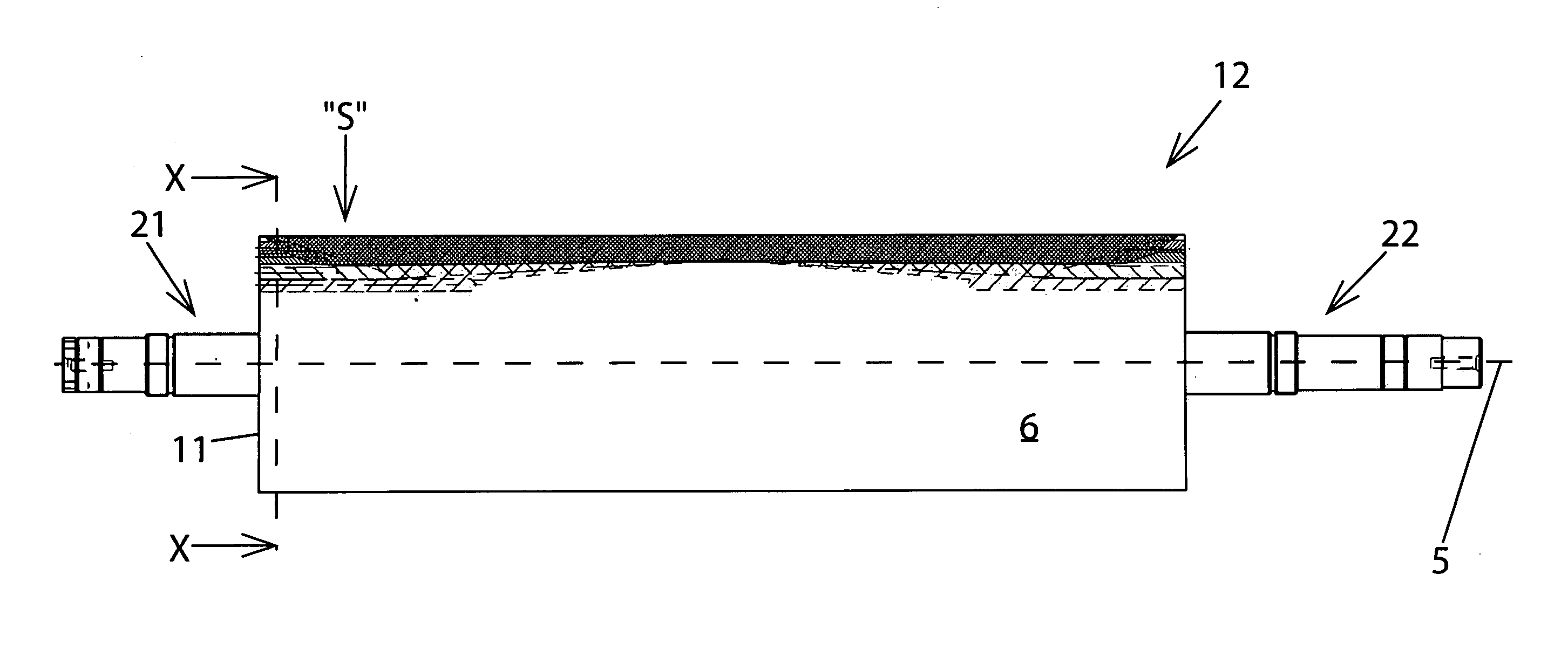
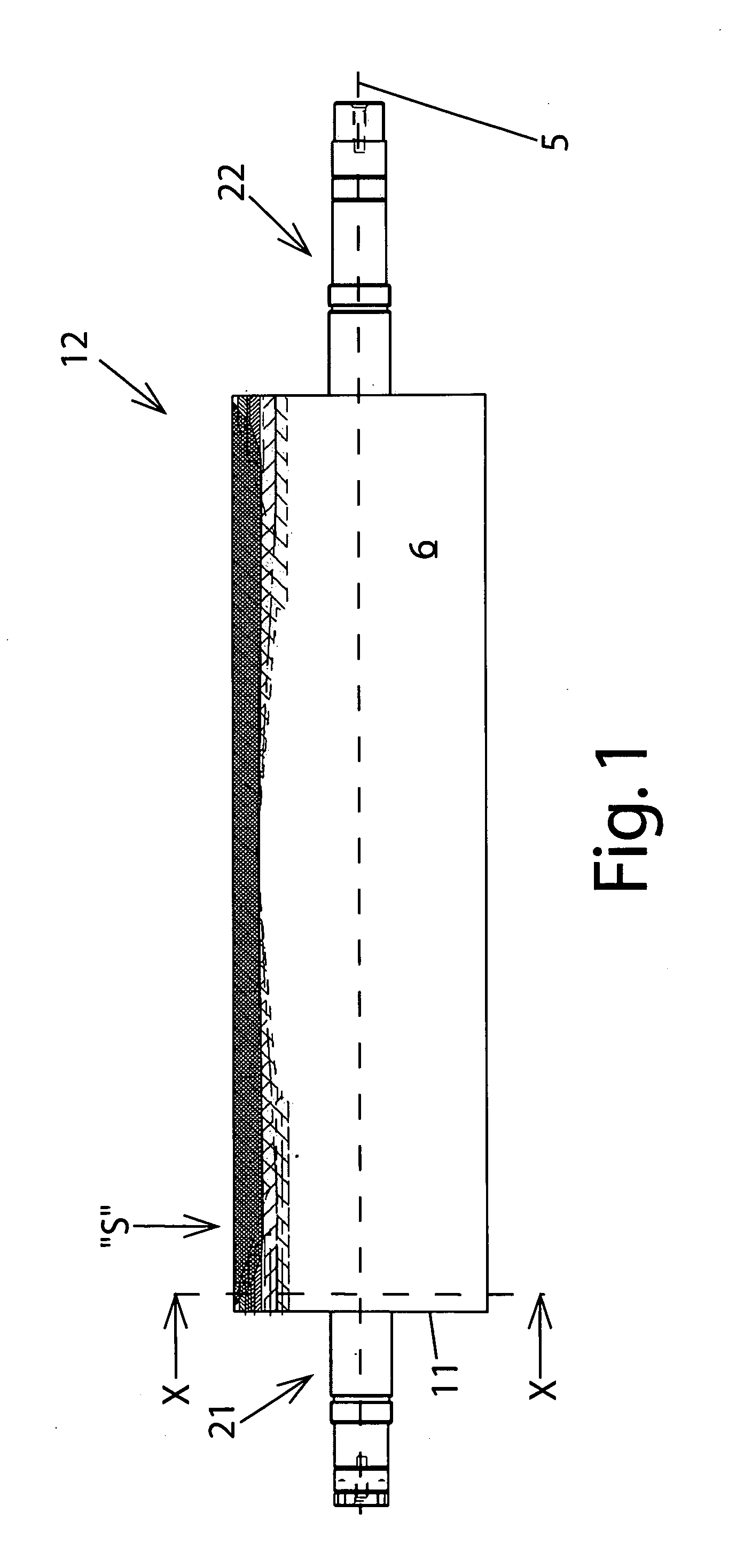
[0021]FIG. 1 is a side view of an embodiment of the suction roller according to the invention, with suction slits shown as examples, as well as without a slit cover;

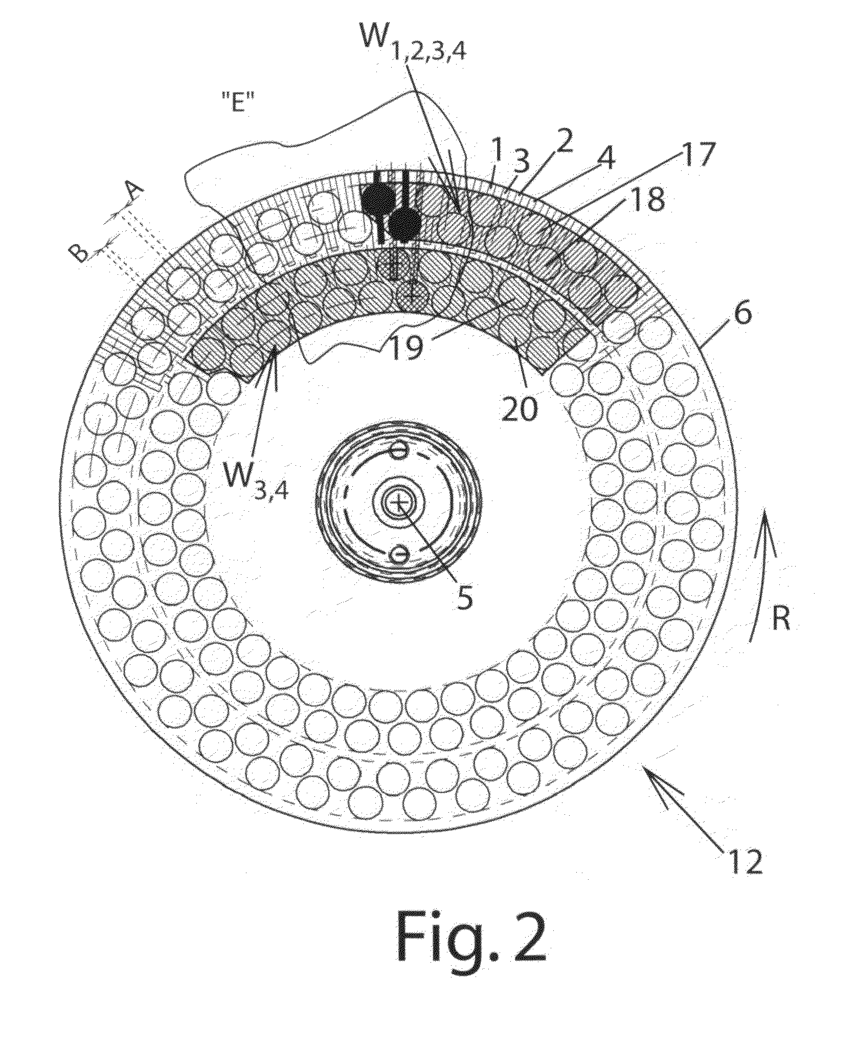
[0022]FIG. 2 is a sectional view according to the section X-X in FIG. 1;

[0023]FIG. 3 is an enlarged representation of the detail “E” from FIG. 2, but with a slit cover;

[0024]FIG. 4 is a developed view of a part of the top view “S” of the suction roller indicated in FIG. 1, but with a slit cover;

[0025]FIG. 5 shows various sectional representations through the suction slit according to...


PUM

PropertyMeasurementUnit
widthaaaaaaaaaa
widthaaaaaaaaaa
widthaaaaaaaaaa

Abstract

A suction roller for transporting flat material blanks has a roller axis and a mantle surface. The suction roller is independent of format and therefore can be universally used for transporting flat material blanks, particularly label blanks. The suction roller has controllable suction holes or suction zones that lie at the closest possible distance from one another on its mantle surface. To this end, the suction roller has a plurality of suction slits, which run parallel to the roller axis and open into the mantle surface, whereby at least adjacent suction slits can have suction air applied to them independent of one another, and whereby a slit cover provided with passage holes is disposed on the mantle surface, in such a manner that the passage holes align with the suction slits, at least in part.

Description

CROSS REFERENCE TO RELATED APPLICATIONS[0001]This application claims priority under 35 U.S.C. §119 of German Patent Application No. 10 2007 003 592.8 filed on Jan. 24, 2007.BACKGROUND OF THE INVENTION[0002]1. Field of the Invention[0003]The present invention relates to a suction roller for transporting flat material blanks, particularly such a suction roller for use in connection with a slit cover provided with passage holes. The suction roller according to the invention can particularly be used as a so-called blank separation roller in a label production machine. Applications in envelope production machines are also possible. Specifically, the suction roller can be used in window cutting stations, where window cutouts to be disposed of as waste must be separated from the envelope blanks that are to be processed further.[0004]2. The Prior Art[0005]It is known from DE 103 00 234 B3, in connection with label production, among other things, to use a suction roller as a blank separation...

Claims


Application Information

Patent Timeline
Patent Type & Authority Applications(United States)
IPC IPC(8): B65G39/00B65H29/24B65G39/02B65H20/12B65H27/00
CPCB26D7/018B65H5/226B65H35/08B65H2701/192B65H2406/363B65H2701/1916B65H2406/33
Inventor SCHEU, STEPHAN
Owner WINKLER DUNNEBIER GMBH
Why Eureka
Try Eureka