Cutting system, system for obtaining sample of plant material comprising the same, and method

A cutting system and cutting element technology are applied in the field of systems for obtaining plant material samples, and can solve problems such as inability to realize automation

Active Publication Date: 2017-02-22
RIJK ZWAAN ZAADTEELT & ZAADHANDEL BV
View PDF7 Cites 0 Cited by
  • Summary
  • Abstract
  • Description
  • Claims
  • Application Information

AI Technical Summary

Problems solved by technology

Unfortunately, it has been found that this automation cannot be achieved using the above known systems

Method used


Image

  • Cutting system, system for obtaining sample of plant material comprising the same, and method
  • Cutting system, system for obtaining sample of plant material comprising the same, and method
  • Cutting system, system for obtaining sample of plant material comprising the same, and method

Examples


Embodiment Construction

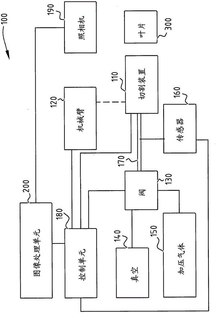
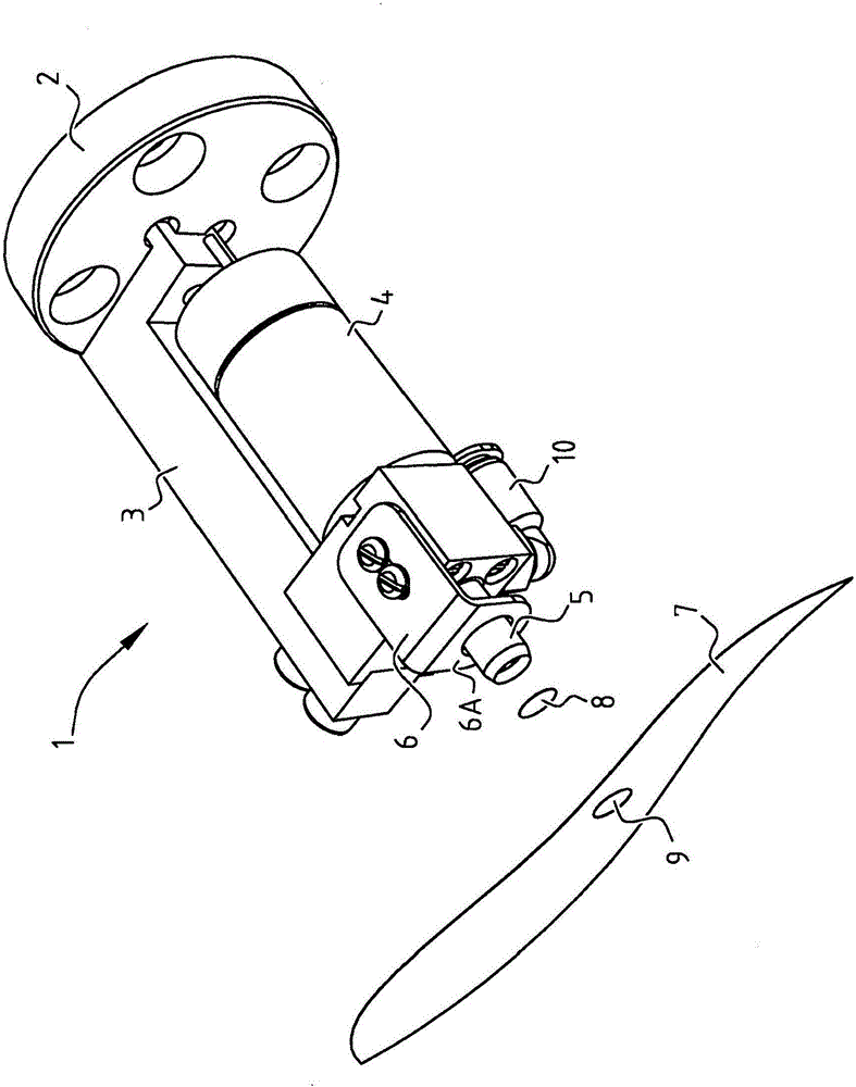
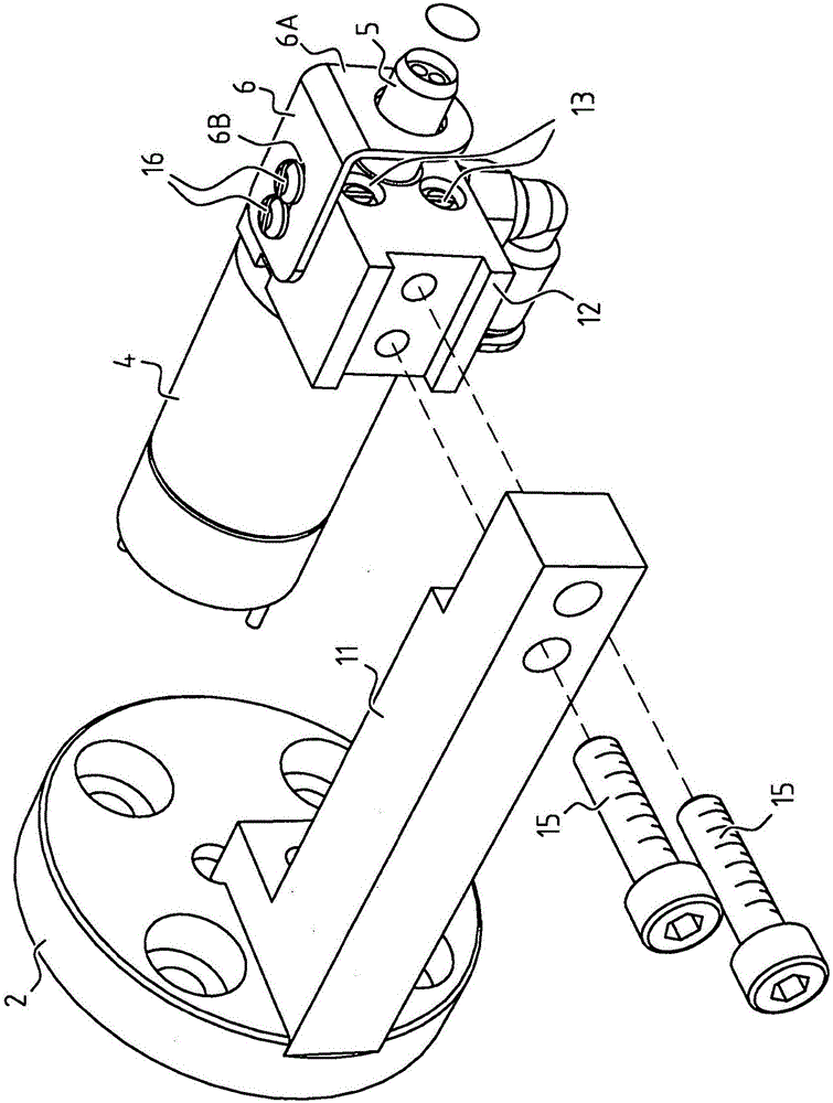
[0044] figure 1 A system 100 according to the invention is shown. The system includes a cutting device 110 . The system is connected to a robotic arm 120 on which the cutting device 110 is mounted. A vacuum source 140 and a pressurized gas source 150 are employed to obtain suction and thrust, respectively. A valve unit 130 is used to switch between the two sources. The sensor 160 is used to measure the pressure in the conduit 170 between the cutting device 110 and the valve unit 130 .

[0045] The system 100 also includes a control unit 180 to control the operation of the robot arm 120 , control the switching operation of the valve unit 130 , and control the driving unit of the cutting device 110 .

[0046] In addition, the system 100 includes one or more optical cameras 190 , and the image output from the optical cameras 190 is processed by the image processing unit 200 . The image output from the image processing unit 200 is output to the control unit 180 .

[0047] Ne...


PUM


Abstract

The present invention is related to a cutting system. It is further related to a system for obtaining a sample of plant material and a method. Such system can for instance be used for DNA analysis as part of a plant breeding program. According to the invention, the cutting system comprises a cutting device having a hollow cutting element having a cutting edge facing a leaf of a plant to be sampled, a drive unit for rotating said cutting element about a longitudinal axis of said cutting element to cut through the leaf, and a gas flow direction unit for applying a suction force through the hollow cutting element. The cutting system further comprises a control unit for controlling the drive unit and the gas flow direction unit. According to the invention, the hollow cutting element is elongated and the control unit is configured to control the gas flow direction unit and the drive unit such that said suction force is applied during said cutting through the leaf, and preferably at least prior to said cutting through the leaf.

Description

technical field [0001] The invention relates to a cutting system. The invention also relates to a system and method for obtaining a sample of plant material. The system can be applied, for example, in DNA analysis as part of a plant breeding program. An example of such a device is known from US 7,980,148. Background technique [0002] Known devices use punch rods to punch samples out of plant leaves. Before the stamping operation, the blade must be inserted in the opening between the stamping rod and the support element. Support elements are required to prevent the blades from moving away during the stamping process. [0003] With said known device, the user has to manipulate the device manually in order to insert the blade in the opening defined between the stamped rod and the support element. This prevents the use of the device in fully automated sampling systems. [0004] A growing trend in plant breeding is to use DNA sampling to predict or analyze plant traits usi...

Claims


Application Information

Patent Timeline
IPC IPC(8): G01N1/08
CPCG01N1/08G01N2001/2873G01N2001/288G01N1/286
Inventor A·J·C·博韦
Owner RIJK ZWAAN ZAADTEELT & ZAADHANDEL BV
Why Eureka
Try Eureka