Multi-Optical Axis Photoelectric Sensor

a photoelectric sensor and optical axis technology, applied in the direction of counting objects on conveyors, instruments, mechanical equipment, etc., can solve the problems of operator's inability to know whether the multi-optical axis photoelectric sensor has been prepared for receiving the interlock reset signal, safety regulations may not permit one to control the safety component via a non-safety controller

Inactive Publication Date: 2008-07-31
KEYENCE
View PDF10 Cites 22 Cited by
  • Summary
  • Abstract
  • Description
  • Claims
  • Application Information

AI Technical Summary

Benefits of technology

[0034]As one of the preferred embodiments, a multi-optical axis photoelectric sensor has a muting lamp port for directly connecting to a muting lamp. The muting lamp port does not only provide current for the connected muting lamp, but is also connected to a detecting circuit for inspecting the current passing into the lamp. When the current passed into the lamp is not normal, the statu

Problems solved by technology

In such a case, productivity may decrease.
However, the operator can not know whether the multi-optical axis photoelectric sensor has been prepared for receiving the interlock reset signal or not.
To control the multi-optical axis photoelectric

Method used


Image

  • Multi-Optical Axis Photoelectric Sensor
  • Multi-Optical Axis Photoelectric Sensor
  • Multi-Optical Axis Photoelectric Sensor

Examples


first embodiment

Multi-Optical Axis Photoelectric Sensor 1:

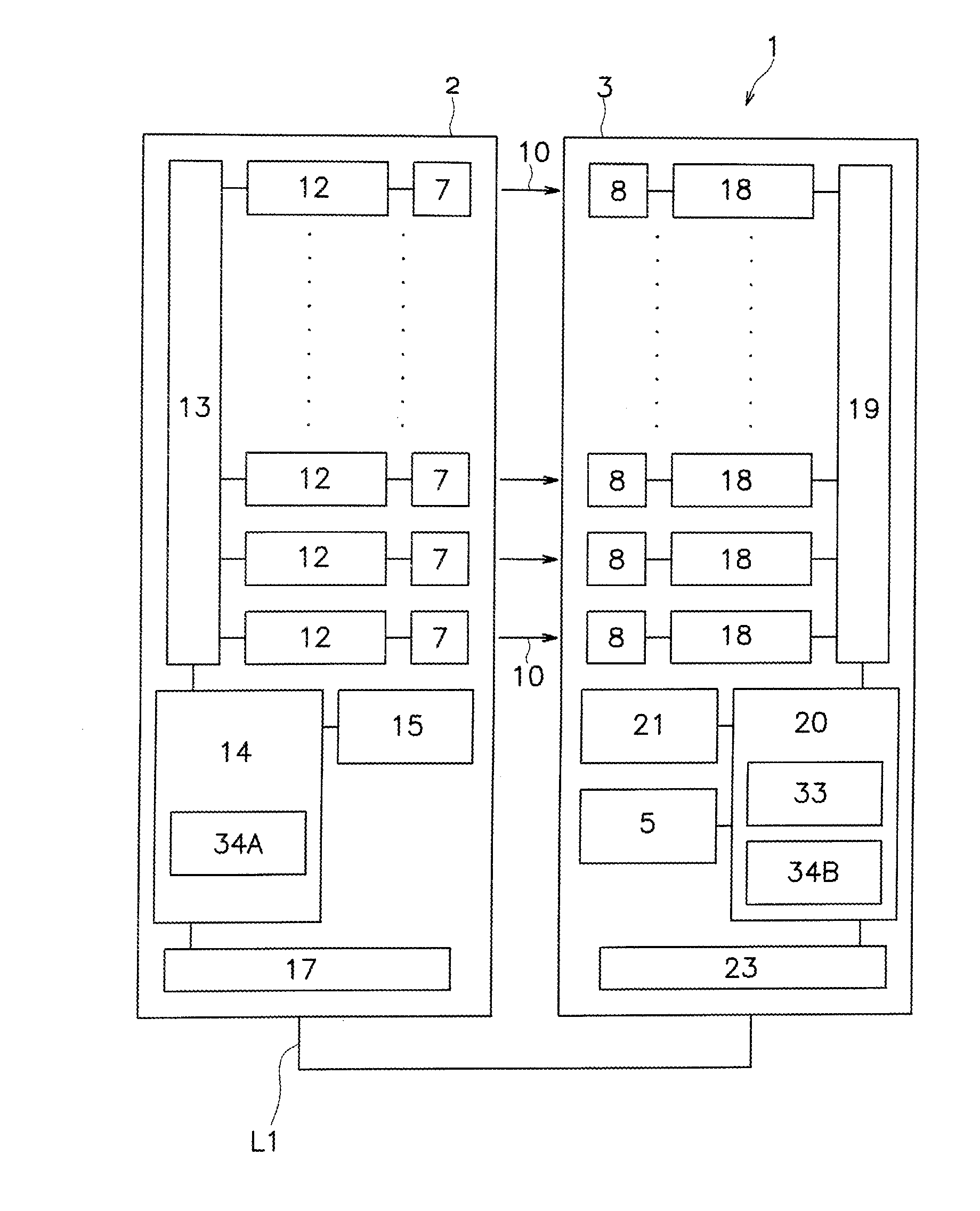
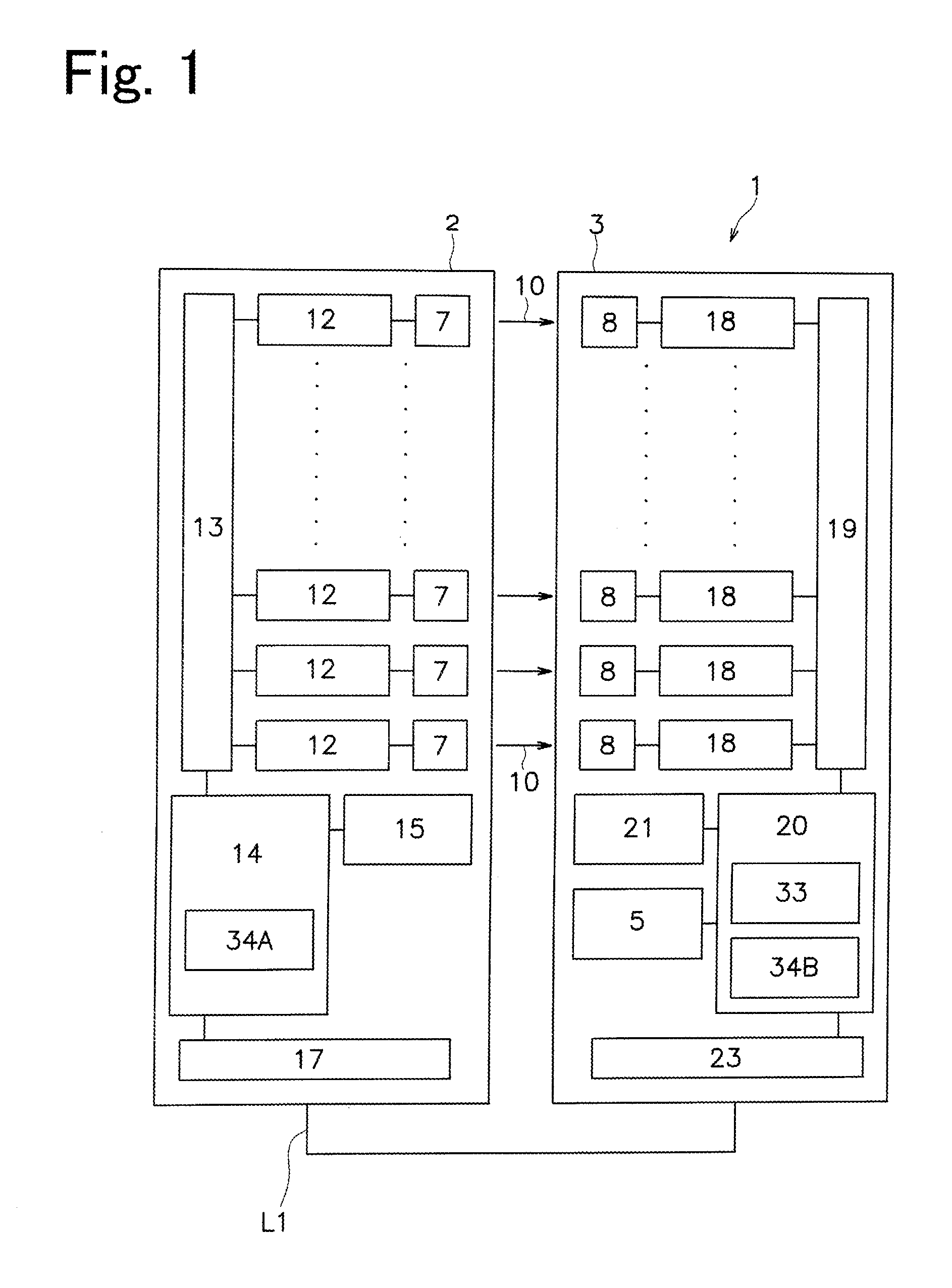
[0056]In FIG. 1, a multi-optical axis photoelectric sensor 1 of the present invention includes a pair of an emitting unit 2 and a receiving unit 3, and controller 5 is installed in the receiving unit 3. The controller 5 is connected to the emitting unit 2 via a communication line or a signal line L1.

[0057]The emitting unit 2 and the receiving unit 3 are arranged in a plane and faces to each other in a plane. A plurality of light beams such as infrared light beams are emitted from each of a plurality of emitting elements 7 of the emitting unit 2 to each of a plurality of receiving elements 8, corresponding to each of the plurality of emitting elements 7, of the receiving unit 3. Consequently, a safety light curtain is formed between the emitting unit 2 and the receiving unit 3. Reference number 10 as shown in FIG. 10 represents a light axis.

[0058]The emitting element 7 constitutes, for example, a light emitting diode (LED) emitting an infrare...


PUM


Abstract

The present invention can be used in a multi-optical axis photoelectric sensor indicating an operating status thereof to a non-safety control device. The present invention allows the multi-optical axis photoelectric sensor so as to become a easier operation. The multi-optical axis photoelectric sensor has a control unit to providing a safety control signal representing a result of a distinguish portion in a normal operating status, a safety control signal representing operation non-allowable in an abnormal status and a safety control signal representing operation allowable in a special operating status. The multi-optical axis photoelectric sensor also has an operating status indication portion for determining an operating status of the multi-optical axis photoelectric sensor from the normal operating status, the abnormal status and the special operating status, and providing the operating status to an external device via the same output line regardless of the result of the determination.

Description

CROSS-REFERENCE TO RELATED APPLICATION[0001]The present application claims priority from Japanese Patent Application No. 2007-015148, filed on Jan. 25, 2007, the entire contents of which are hereby incorporated by reference.BACKGROUND OF THE INVENTION[0002]1. Field of the Invention[0003]The present invention relates to a multi-optical axis photoelectric sensor forming a light curtain for detecting a human body and the like penetrating into a predetermined area. In more detail, the present invention relates to an output of the multi-optical axis photoelectric sensor provided for a non-safety control device.[0004]2. Description of the Related Art[0005]In general cases, a multi-optical axis photoelectric sensor for detecting a human body and the like, is utilized where a person can come in contact with a hazardous source, thereby providing safety to the person in view of a machine which is assessed as the hazardous source such as a press machine. The multi-optical axis photoelectric se...

Claims


Application Information

Patent Timeline
IPC IPC(8): H01J40/14
CPCF16P3/14F16P3/144G01V8/20
Inventor INOUE, TETSUFUKUMURA, KOJI
Owner KEYENCE
Why Eureka
Try Eureka