Bi-Modal Remote Identification System

Inactive Publication Date: 2008-07-31
FLEXTECH SYST
View PDF62 Cites 27 Cited by
  • Summary
  • Abstract
  • Description
  • Claims
  • Application Information

AI Technical Summary

Problems solved by technology

Active RFID systems often employ a transmitter device that requires a battery and are significantly more expensive than corresponding passive RFID transmitters.
Passive RFID transmitters also often require expensive detectors and a significantly reduced detection range, which is typically between several inches

Method used


Image

  • Bi-Modal Remote Identification System
  • Bi-Modal Remote Identification System
  • Bi-Modal Remote Identification System

Examples


Embodiment Construction

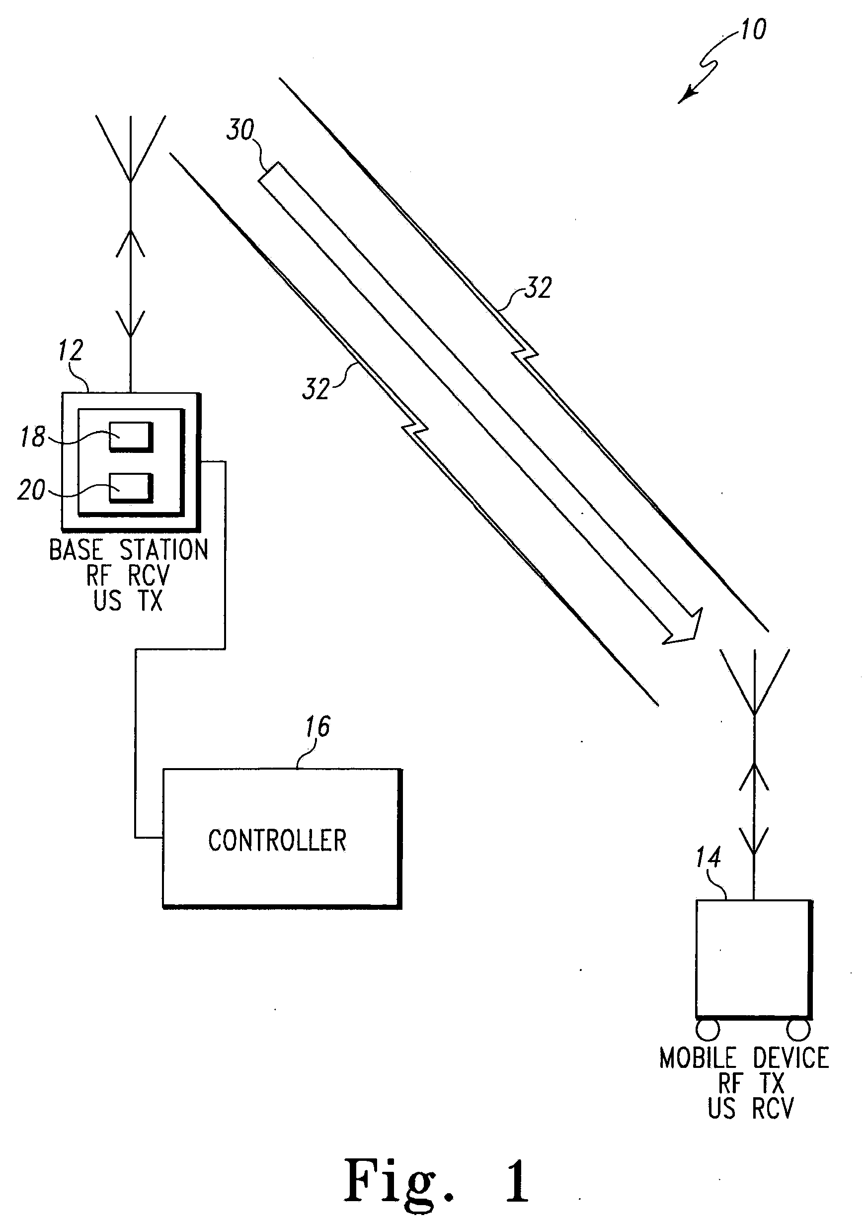
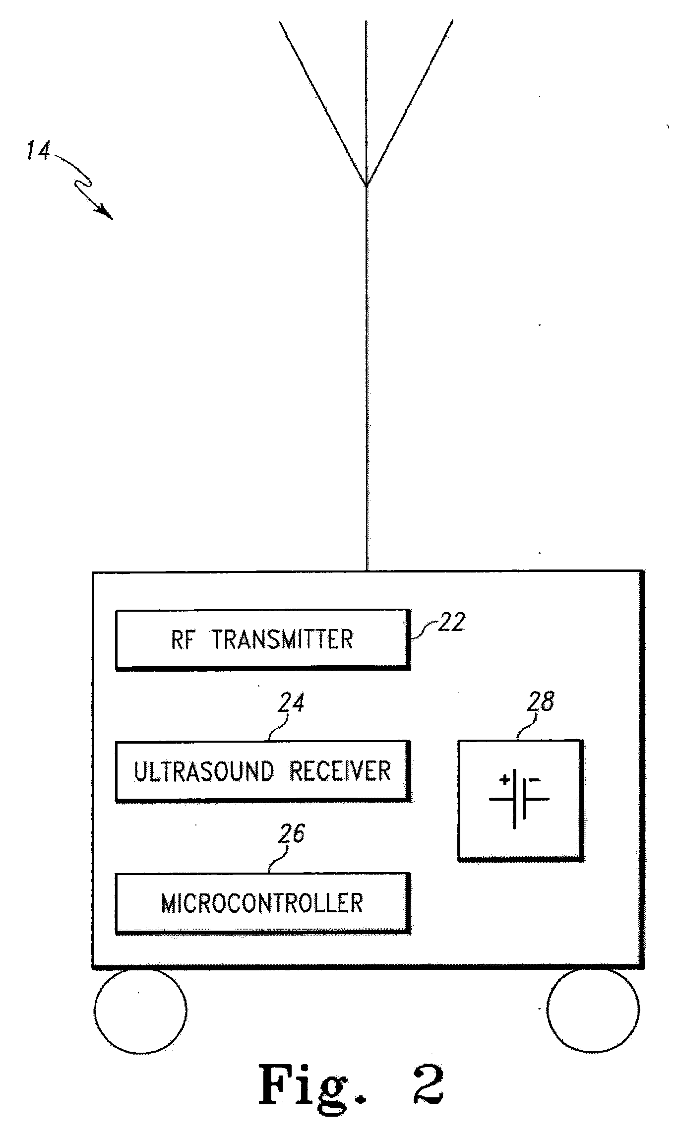
[0021]Referring to FIGS. 1-2, an illustrative example of the system 10 is shown. The system 10 includes a base unit 12, a mobile device 14, and a controller 16. The base unit 12 includes a radio frequency (RF) receiver 18 and an ultrasound transmitter 20. The RF receiver 18 receives RF signals and the ultrasound transmitter 20 sends ultrasound signals in alternate time frames. Alternatively, the controller 16 can be integral with the base unit 12.

[0022]The base unit 12 is connected to a substantial power supply. The base unit 12 is stationary, which can include integration with a wall, ceiling, floor, or some other non-movable fixture within a room or defined area within a building. An exemplary placement would be integrated within the wall of room in a healthcare facility. Power supplied to the base unit 12 is substantial and can be internal to the building and / or a portable battery (not shown). Integrated with the device 12 is the receiver 18, which acts as a listening device for ...


PUM


Abstract

A novel bi-modal remote identification system is described. In at least one embodiment the system includes a base unit, a mobile unit, and a processor. The base unit and mobile unit utilize both radio frequency and ultrasound wireless technologies for remotely identifying the location of assets.

Description

CROSS-REFERENCE TO RELATED APPLICATIONS[0001]This application claims priority to U.S. Provisional Application Ser. No. 60 / 871,344, filed Dec. 21, 2006, U.S. Provisional Application Ser. No. 60 / 871,356, filed Dec. 21, 2006, U.S. Provisional Application Ser. No. 60 / 864,628, filed Nov. 7, 2006, U.S. Provisional Application Ser. No. 60 / 864,626, filed Nov. 7, 2006, and co-pending Non-Provisional Patent Application titled “Digital Intercom Based Data Management System”, attorney docket number FT-34057, and filed on Nov. 7, 2007, each application is fully incorporated by reference herein.STATEMENT REGARDING FEDERALLY SPONSORED RESEARCH OR DEVELOPMENT[0002]The U.S. Government has certain rights in this invention as provided for by the terms of Grant No. R44 AG019528 awarded by the National Institutes of Health.FIELD OF INVENTION[0003]The present invention relates to identification systems, and more particularly relates to bi-modal remote identification systems employing radio frequency iden...

Claims


Application Information

Patent Timeline
IPC IPC(8): H04Q5/22
CPCG06F19/322G10L15/30G06F19/327G06F19/323G16H40/20G16H10/65G16H10/60
Inventor FLAX, STEPHEN W.
Owner FLEXTECH SYST
Why Eureka
Try Eureka