Liquid transport apparatus and method for producing liquid transport apparatus
- Summary
- Abstract
- Description
- Claims
- Application Information
AI Technical Summary
Benefits of technology
Problems solved by technology
Method used
Image

Examples
third modified embodiment
[0128]When it is unnecessary to progressively suppress the mutual interference between the pressure-applying portion and the opening / closing portion, for example, when the distance between the pressure-applying portion and the opening / closing portion is sufficiently far, then it is unnecessary to provide any rigidity-lowered portion for the stack for constructing the piezoelectric actuator. In other words, as shown in FIGS. 14 and 15, it is also allowable that no recess is formed for a vibration plate 35C, neither through-hole nor recess is formed for a piezoelectric material layer 36C as well, and the piezoelectric material layer 36C is formed continuously while ranging over the pressure chamber 23, the ink supply flow passage 24, and the ink discharge flow passage 25 (third modified embodiment). In this arrangement, it is unnecessary to perform the step of forming the recess for the vibration plate and the step of forming the through-hole and / or the recess for the piezoelectric ma...
fourth modified embodiment
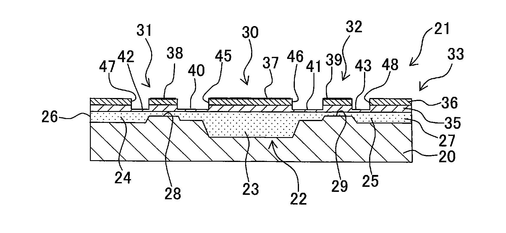
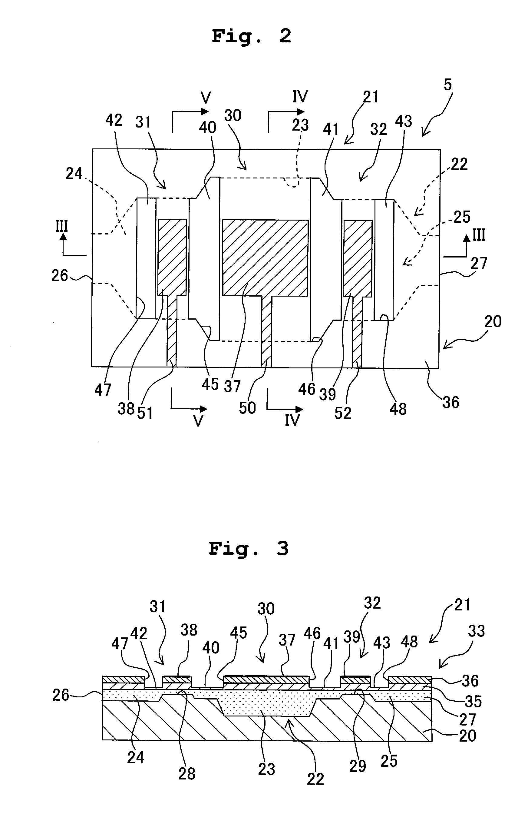
[0129]As shown in FIGS. 16 and 17, recesses 40D to 43D, which are provided to locally lower the rigidity of a stack 33D, may be formed on the lower surface of a vibration plate 35D (fourth modified embodiment). However, in this arrangement, if any bubble is mixed into the ink, the bubble tends to stay in the recesses 40D to 43D. Therefore, it is feared that the desired pressure cannot be applied to the ink by means of the pressure-applying portion. On the other hand, when the recesses 40 to 43 are formed on the upper surface of the vibration plate 35 (surface disposed on the side not facing the base member) as in the embodiment described above, the lower surface of the vibration plate 35, which makes contact with the ink, is the flat surface. Therefore, the bubble hardly stays (see FIG. 3). From this viewpoint, it is preferable that the recesses are formed on the upper surface of the vibration plate.
fifth modified embodiment
[0130]In the embodiment described above, the piezoelectric material layer 36 is formed to the area outside the ink flow passage 22 including, for example, the pressure chamber 23. Therefore, the deformation of the piezoelectric material layer 36 is restricted, and the amount of displacement of the vibration plate 35 is decreased in the area facing the ink flow passage 22. Accordingly, as shown in FIGS. 18 and 19, it is also allowable that a piezoelectric material layer 36E is formed in only areas of the upper surface of a vibration plate 35E facing the pressure chamber 23 and the valve seats 28, 29 (fifth modified embodiment).
[0131]Also in the fifth modified embodiment, wirings 50E to 52E, which are independent from each other, are led from the three electrodes 37 to 39 formed on the upper surface of the piezoelectric material layer 36E. However, the wirings 50E to 52E cannot be led to the area outside the ink flow passage 22 (conduction is caused with the upper surface of the vibra...
PUM
 Abstract
Description
Claims
Application Information