Thermalization arrangement at cryogenic temperatures

Pending Publication Date: 2022-08-25
TEKNOLOGIAN TUTKIMUSKESKUS VTT OY
View PDF0 Cites 0 Cited by
  • Summary
  • Abstract
  • Description
  • Claims
  • Application Information

AI Technical Summary

Benefits of technology

[0010]The invention improves the cooling or thermalization of the device/s or component/s on the surface of the substrate by eliminating the reflections of phonons in the substrate and by making it possible to absorb the energy of the phonons by the elec

Problems solved by technology

Cryogenic devices are delicate sensors and other devices.
Therefore, a phonon transmitting energy from the device/component on the surface of the substrate may reflect back into the substrate from said inter

Method used


Image

  • Thermalization arrangement at cryogenic temperatures
  • Thermalization arrangement at cryogenic temperatures
  • Thermalization arrangement at cryogenic temperatures

Examples


Example

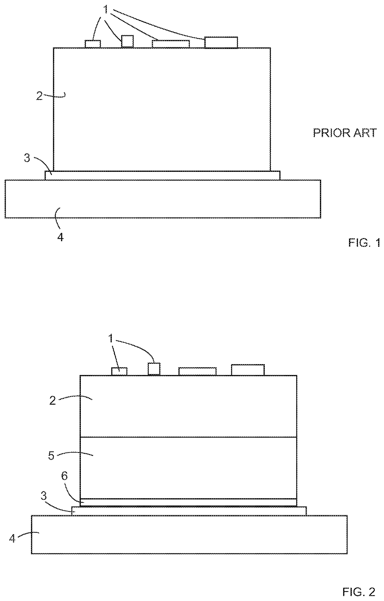
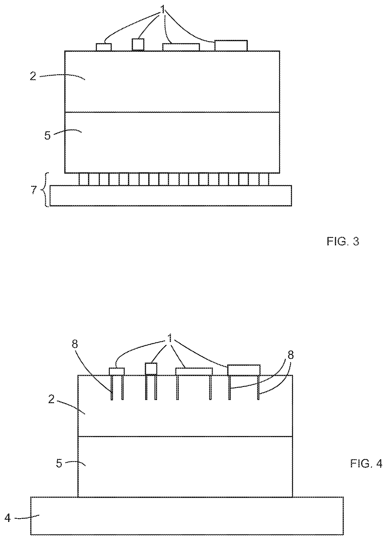
[0022]FIG. 2 illustrates an example of an inventive thermalization arrangement at cryogenic temperatures. The devices or their components 1 to be cooled / thermalized are on a substrate. The device or devices are electrical devices, like sensors or quantum components, such as qubits, etc. The component or components are electrical components like resistors, capacitors, inductors, tunnel junctions, superconducting components etc. More precisely, the substrate is dielectric substrate 2 layer on which substrate a device / s or component / s 1 have been fabricated or are attached on, for example, using flip-chip technique.

[0023]The substrate is, for example, silicon-based material having normally thickness ranging from 200 μm to 1 mm. For example, silicon, silicon-oxide, silicon-nitride or their combination are materials used as a wafer (substrate). The used materials for the substrate are dielectric or semiconducting as non-degenerately doped semiconductors become dielectrics at sufficiently...


PUM


Abstract

An inventive embodiment comprises a thermalization arrangement at cryogenic temperatures. The arrangement comprises a dielectric substrate (2) layer on which substrate a device/s or component/s (1) are positionable. A heat sink component (4) is attached on another side of the substrate. The arrangement further comprises a conductive layer (5) between the substrate layer (2) and the heat sink component (4). A joint between the substrate layer (2) and the conductive layer (5) has minimal thermal boundary resistance. Another joint between the conductive layer (5) and the cooling heat sink layer (4) is electrically conductive.

Description

PRIORITY[0001]This application claims priority of Finnish national application 20215201 filed on Feb. 23, 2021, the content of which is incorporated herein by reference.FIELD OF TECHNOLOGY[0002]The invention relates to a thermalization arrangements at cryogenic temperatures. Especially, the invention relates to in-chip arrangements.BACKGROUND OF THE INVENTION[0003]Cryogenic temperatures may be defined to mean temperatures ranging from 93 K (kelvin) to zero K (absolute zero), but also different values are used. In general, cryogenics refers to technology for achieving very low temperatures in order to study behavior of materials and phenomenon at very low temperatures and to create proper operating conditions for different cryogenic devices.[0004]Cryogenic devices are delicate sensors and other devices. In comparison to room temperature, cryogenic temperatures bring in significant reduction of thermal noise, thereby improving resolution and sensitivity of sensors and other devices, f...

Claims


Application Information

Patent Timeline
IPC IPC(8): H05K7/20F28F21/08
CPCH05K7/20509F28F21/08F28F2013/006H05K7/20481H05K7/20372H01L23/3738H01L23/373F25D19/006F25B21/00H10N60/10
Inventor PRUNNILA, MIKARONZANI, ALBERTOMYKKÄNEN, EMMAKEMPPINEN, ANTTILEHTINEN, JANNE
Owner TEKNOLOGIAN TUTKIMUSKESKUS VTT OY
Why Eureka
Try Eureka