Ozone Generation With Directly Cooled Plasma Channels

Active Publication Date: 2018-11-01
XYLEM IP MANAGEMENT SARL
View PDF5 Cites 0 Cited by
  • Summary
  • Abstract
  • Description
  • Claims
  • Application Information

AI Technical Summary

Benefits of technology

[0008]It is the object of the present invention to provide an ozone generator which exhibits a good transport of heat in the discharge gap. It is also the object of the i

Problems solved by technology

Their limiting factor in terms of heat transport is the thermal conductivity within the discharge gap.
The whole co

Method used


Image

  • Ozone Generation With Directly Cooled Plasma Channels
  • Ozone Generation With Directly Cooled Plasma Channels
  • Ozone Generation With Directly Cooled Plasma Channels

Examples


Example

DETAILED DESCRIPTION OF THE FIGURES

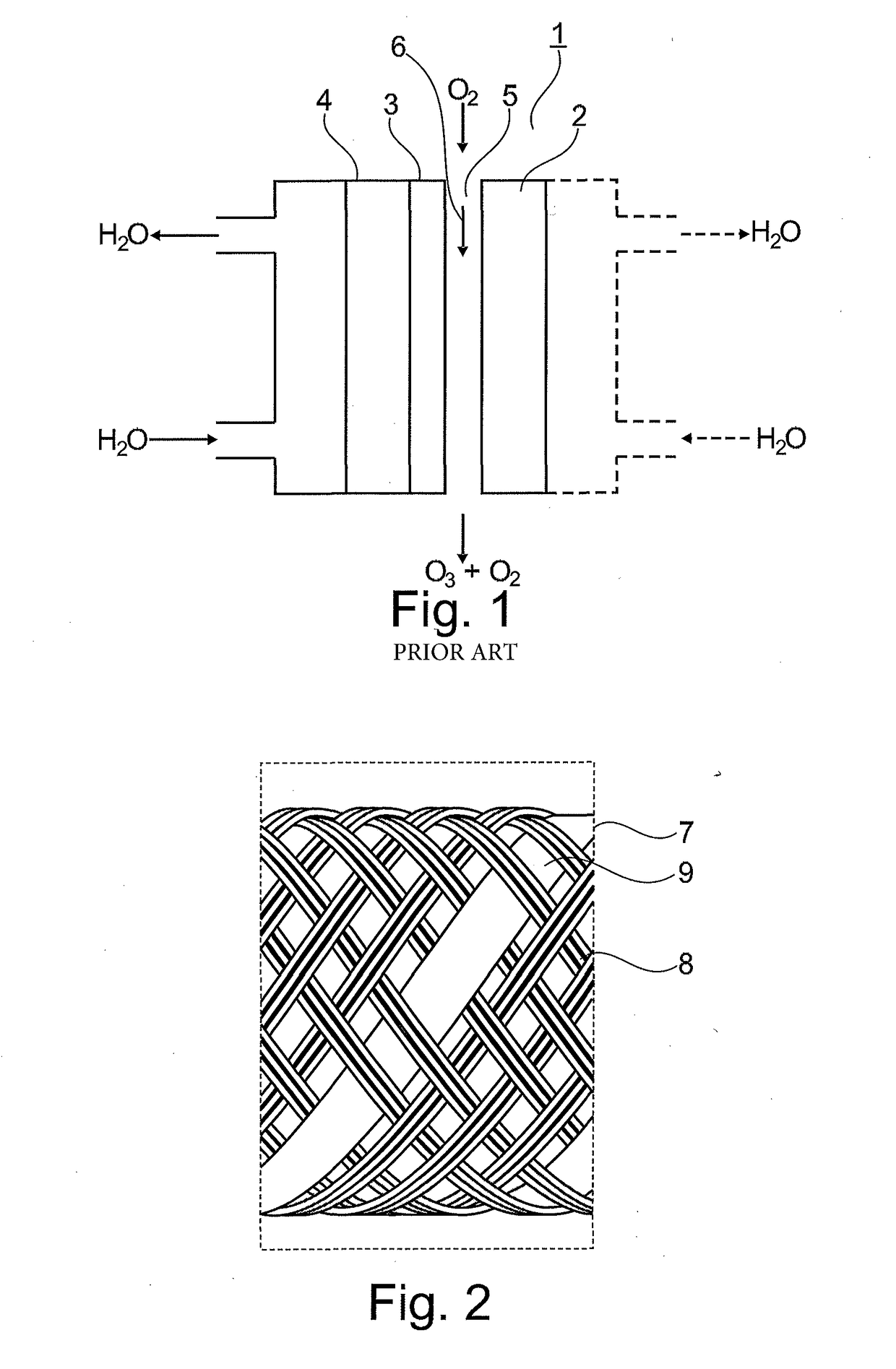
[0024]FIG. 1 shows a schematic cross-section of an electrode arrangement of a single-gap ozone generator 1 in the construction form of a plate-type ozone generator without a fabric arranged in the gap. In this respect, FIG. 1 corresponds to the prior art. Such ozone generators 1 can be designed as plate-type ozone generators or tube-type ozone generators, depending on the field of application.

[0025]Plate-type ozone generators have a high voltage electrode 2 and at least one counter electrode 4 which are plate-formed in design. The electrodes 2, 4 limit a gap 5 through which an oxygen-containing gas 6 flows and in which a dielectric 3 is arranged. Conventionally, plate-type ozone generators are cooled on one or two sides by a cooling medium passed along the outer sides of the electrodes 2, 4. Air and water are used as cooling media.

[0026]Tube-type ozone generators are conventionally used in an ozone generator in groups. The ozone generators are ther...


PUM


Abstract

An ozone generator with a high voltage electrode and at least one counter electrode which limit a gap in which at least one dielectric and an electrically non-conductive structure are arranged and through which a stream of gas flows in a direction of flow. The high voltage electrode and the at least one counter electrode are provided with a connection for an electrical voltage supply in order to generate silent discharges. The electrically non-conductive structure contains pores with a nominal pore size (x) of 100 μm<x<1 mm.

Description

CROSS-REFERENCE TO RELATED APPLICATIONS[0001]This patent application is a U.S. National Phase Patent Application of PCT Application No.: PCT / EP2016 / 075106, filed Oct. 19, 2016, which claims priority to European Patent Application No. 15190727.6, filed Oct. 21, 2015, each of which is incorporated by reference herein in its entirety.FIELD OF THE INVENTION[0002]The present invention relates to an ozone generator with a high voltage electrode and at least one counter electrode which limit a gap in which at least one dielectric and an electrically non-conductive structure are arranged, and the corresponding non-conductive structure.BACKGROUND OF THE INVENTION[0003]The efficiency of ozone generators depends to a great extent on the temperature in the discharge gap. On the one hand, this is due to the fact that the ozone-formation reaction proceeds better at low temperatures, and on the other hand the kinetics of the ozone depletion mechanism increase exponentially with the temperature. An...

Claims


Application Information

Patent Timeline
IPC IPC(8): C01B13/11
CPCC01B13/11C01B2201/22C01B2201/24C01B2201/32C01B2201/70
Inventor FIEKENS, RALFFIETZEK, REINERSALVERMOSER, MANFREDBRUGGEMANN, NICOLE
Owner XYLEM IP MANAGEMENT SARL
Why Eureka
Try Eureka