Display device

a display panel and display technology, applied in the field of display panels, can solve the problems of large picture frame sizes, and achieve the effect of reducing the vertical picture frame size of the display panel

Inactive Publication Date: 2008-08-07
PANASONIC LIQUID CRYSTAL DISPLAY CO LTD +1
View PDF3 Cites 0 Cited by
  • Summary
  • Abstract
  • Description
  • Claims
  • Application Information

AI Technical Summary

Benefits of technology

[0045]To briefly explain advantageous effects obtained by typical inventions among the inventions disclosed in this specification, they are as follows.
[0046]According to the display device of the present invention, it is possible to mount the video line drive circuit on a lateral side of the display panel while reducing a vertical picture frame size of the display panel.

Problems solved by technology

However, when the conventional video line drive circuit (DRV) is mounted on the lateral side of the liquid crystal display panel (PNL), it is necessary to arrange connection lines for connecting the video lines (VL1 to VLn) and video voltage output terminals of the video line drive circuit (DRV) on an upper side or a lower side of the liquid crystal display panel (PNL) and hence, there arises a drawback that the picture frame size becomes large.

Method used


Image

  • Display device
  • Display device
  • Display device

Examples


Embodiment Construction

[0055]Hereinafter, an embodiment of the present invention is explained in detail in conjunction with drawings.

[0056]Here, in all drawings for explaining the embodiment, parts having identical functions are given same symbols and their repeated explanation is omitted.

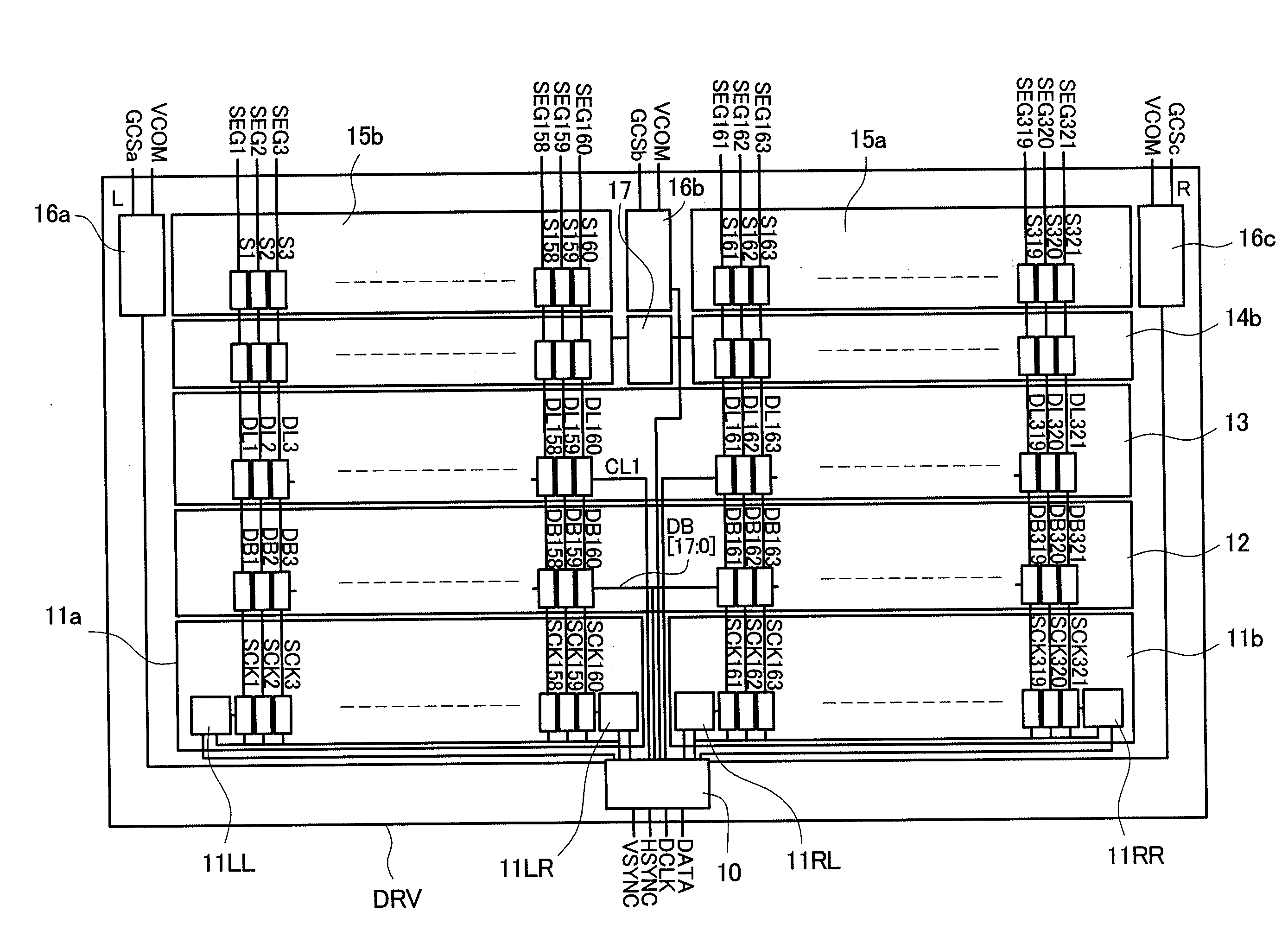
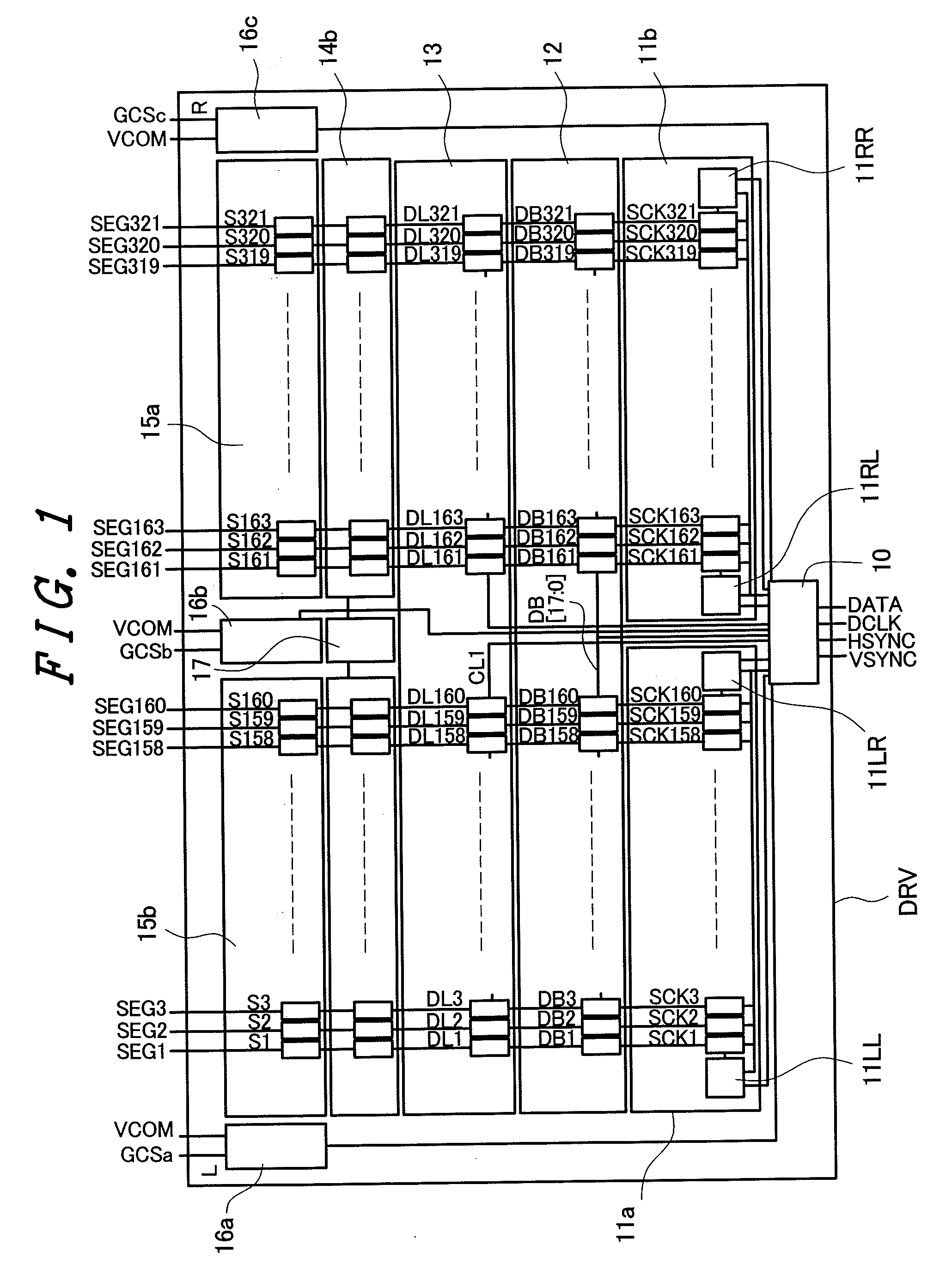
[0057]FIG. 1 is a block diagram showing the schematic constitution of a video line drive circuit (DRV) according to an embodiment of the present invention. As shown in FIG. 1, the video line drive circuit (DRV) of this embodiment includes a control circuit 10, a shift register circuit (11a, 11b), a bit latch circuit 12, a line latch circuit 13, a D / A converting circuit (14a, 14b), an output circuit (15a, 15b), a scanning line control signal / counter voltage generating circuit (16a, 16b, 16c) and a gradation voltage generating circuit 17.

[0058]In this embodiment, display data (DATA) inputted from the outside is constituted of 18 bits (6 bits for each color of R, G, B). The gradation voltage generating circuit 17 generates ...


PUM


Abstract

A display device mounts a video line drive circuit on a lateral side of a display panel while reducing a vertical picture frame size of the display panel. A display device includes: a display panel having a plurality of video lines; and a video line drive circuit which supplies a video voltage to the respective video lines, the video line drive circuit including a control circuit and a shift register circuit which outputs a plurality of acquisition pulses, wherein the shift register circuit is divided into two shift resister circuits consisting of a first shift register circuit and a second shift register circuit, the first shift register circuit forms a first operation control circuit on one end thereof and a second operation control circuit one another end thereof, the second shift register circuit forms a third operation control circuit on one end thereof and a fourth operation control circuit one another end thereof, and the control circuit selects one operation control circuit out of the first operation control circuit and the second operation control circuit of the first shift register circuit and inputs a start pulse to the selected operation control circuit, and selects one operation control circuit out of the third operation control circuit and the fourth operation control circuit of the second shift register circuit and inputs a start pulse to the selected operation control circuit.

Description

CLAIM OF PRIORITY[0001]The present application claims priority from Japanese application serial No. 2007-25483 filed on Feb. 5, 2007, the content of which is hereby incorporated by reference into this application.BACKGROUND OF THE INVENTION[0002]1. Field of the Invention[0003]The present invention relates to a display device, and more particularly to a display device which includes a video line drive circuit (drain driver) mountable on a short side or a long side of a display panel.[0004]2. Description of the Related Art[0005]As a high-definition color monitor of a computer or other information equipment or a display device of a television receiver set, a liquid crystal display module has been popularly used.[0006]The liquid crystal display module basically includes a so-called liquid crystal display panel which sandwiches a liquid crystal layer between two (a pair of) substrates, wherein at least one of the substrates is made of transparent glass or the like. By selectively applyin...

Claims


Application Information

Patent Timeline
Patent Type & Authority Applications(United States)
IPC IPC(8): G06F3/038
CPCG09G3/20G09G3/3208G09G3/3666G09G2330/021G09G2310/027G09G2310/0297G09G2310/08G09G2300/0443
Inventor YOSHIMOTO, TAKASHINAGAO, SHOUJIKIDA, HIDETOSHI
Owner PANASONIC LIQUID CRYSTAL DISPLAY CO LTD
Why Eureka
Try Eureka