Display Apparatus

a display device and liquid crystal technology, applied in the field of display devices, can solve the problems of not being able to obtain satisfactory image quality, and achieve the effects of reducing the size of the display device, reducing the amount of data to be stored, and reducing the required memory capacity

Active Publication Date: 2009-05-14
SHARP KK
View PDF5 Cites 5 Cited by
  • Summary
  • Abstract
  • Description
  • Claims
  • Application Information

AI Technical Summary

Benefits of technology

[0023]According to the first aspect of the invention, the applied gradation value determination table has stored therein a plurality of gradation values, a plurality of gradation section values indicating a plurality of gradation sections into which the gradation values are classified in accordance with one or more thresholds, and output values corresponding to combinations of the gradation values and the gradation section values. Therefore, the quantity of data that are to be stored can be significantly reduced compared to conventional applied gradation value determination tables in which the gradation values are not classified into a plurality of gradation sections. Thus, the required memory capacity can be reduced, making it possible to reduce the size of display devices more easily than in the conventional art.
[0024]According to the second aspect of the invention, the applied gradation value determination table has stored therein gradation section values that are to be correlated with externally inputted image signals, gradation section values that are to be correlated with an image signal inputted one frame earlier, and output values corresponding to combinations of the two types of gradation section values. Therefore, the quantity of data that is to be stored in the applied gradation value determination table can be reduced more than in the first aspect of the invention. Thus, it is possible to further reduce the size of the display devices.
[0025]According to the third aspect of the invention, the frame data storage unit has stored therein gradation section values for one screen image. Therefore, the size of data that is to be stored can be smaller than those in conventional frame data storage units in which gradation values for one screen image are stored. Thus, the required memory capacity can be reduced, making it possible to reduce the size of the display devices.
[0026]According to the fourth aspect of the invention, the gradation section setting table is provided in order to classify the gradation values into a plurality of gradation sections. Therefore, it is possible to readily set and change the gradation values included in each gradation section.
[0027]According to the fifth aspect of the invention, the applied gradation value determination table and the gradation section setting table are stored in a nonvolatile memory. Therefore, even when the display device is turned off, the contents of the applied gradation value determination table and the gradation section setting table are maintained. Thus, it is possible to eliminate the need to write data to the tables each time the display device is activated.
[0028]According to the sixth aspect of the invention, the applied gradation value is calculated by adding an output value obtained from the applied gradation value determination table to a gradation value corresponding to an externally inputted image signal. Therefore, it is possible to suppress moving images from being displayed in low quality due to low response speed of liquid crystals. Thus, it is possible to reduce the size of the display devices while suppressing image quality deterioration.

Problems solved by technology

However, the liquid crystals are slow in response speed, and therefore in the case of displaying moving images on the liquid crystal display device, it might not be possible to obtain satisfactory image quality.

Method used


Image

  • Display Apparatus
  • Display Apparatus
  • Display Apparatus

Examples


Embodiment Construction

[0051]Hereinafter, an embodiment of the present invention will be described with reference to the accompanying drawings.

[0052]

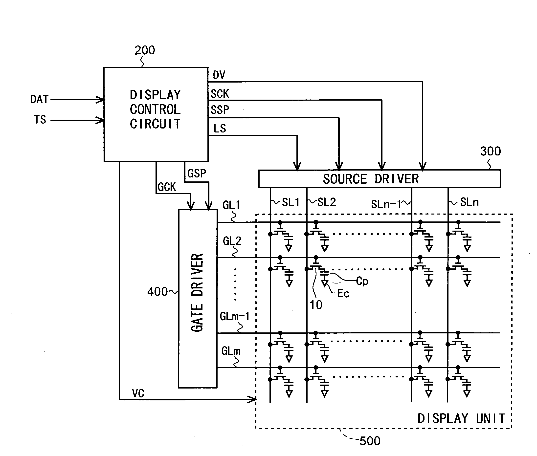
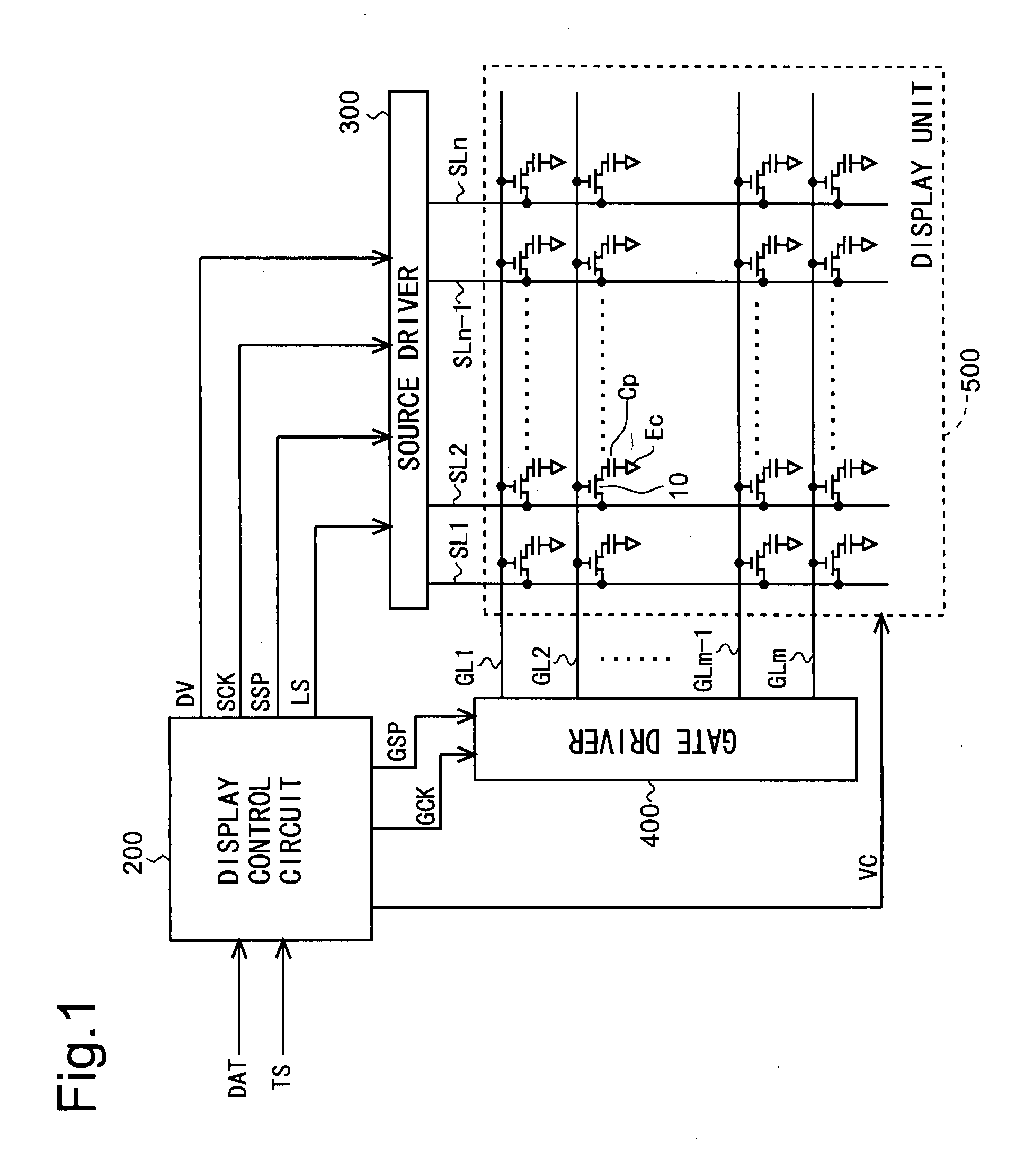
[0053]FIG. 1 is a block diagram illustrating the overall configuration of an active matrix-type liquid crystal display device according to a first embodiment of the present invention. The liquid crystal display device includes a display control circuit 200, a source driver (video signal line drive circuit) 300, a gate driver (scanning signal line drive circuit) 400, and a display unit 500. The display unit 500 includes a plurality (n) of video signal lines SL1-SLn, a plurality (m) of scanning signal lines GL1-GLm, and a plurality (n×m) of pixel forming portions provided at their corresponding intersections between the video signal lines SL1-SLn and the scanning signal lines GL1-GLm. Each pixel forming portion is composed of: a TFT 10, which is a switching element having a gate terminal connected to the scanning signal line passing through the corresponding in...


PUM


Abstract

The present invention relates to liquid crystal display devices.
An objective of the present invention is to reduce the size of the liquid crystal display devices, while suppressing moving images from being displayed in low quality.
A threshold table (3) has stored therein thresholds for classifying gradation values, and the gradation values are classified into a plurality of gradation sections in accordance with the thresholds. A look-up table (2) has stored therein differential gradation values corresponding to combinations of gradation section values for data concerning the current frame data and gradation section values for data concerning an immediately preceding frame. A frame memory (21) has stored therein gradation section values for pixels. A control circuit (22) refers to the look-up table (2) and the threshold table (3) to calculate a differential gradation value based on a gradation value indicated by image data (DAT) for the current frame and a gradation section value of previous frame data stored in the frame memory (21). A display data calculation circuit (23) calculates an applied gradation value for the current frame data based on the differential gradation value.

Description

TECHNICAL FIELD[0001]The present invention relates to display devices, and particularly to a liquid crystal display device in which overshoot drive is performed in order to suppress poor moving images from being displayed due to low response speed of liquid crystals.BACKGROUND ART[0002]In recent years, there has been strong demand for lighter and thinner displays for personal computers, television sets and the like, and therefore liquid crystal display devices, which readily meet such demand for lighter and thinner displays, have been increasingly employed. However, the liquid crystals are slow in response speed, and therefore in the case of displaying moving images on the liquid crystal display device, it might not be possible to obtain satisfactory image quality. Accordingly, a drive system called “overshoot drive” has been conventionally employed in order to suppress moving images from being displayed in low quality due to the low response speed of the liquid crystals. The oversh...

Claims


Application Information

Patent Timeline
Patent Type & Authority Applications(United States)
IPC IPC(8): G09G3/36
CPCG09G3/3648G09G2320/0252G09G2360/18G09G2340/16G09G2320/0261
Inventor SHIGETA, HIROAKINAKANO, TAKETOSHI
Owner SHARP KK
Why Eureka
Try Eureka