
Display driving circuit

a technology for driving circuits and displays, applied in the field of display driving circuits, can solve the problems of latching, latching, latching, etc., and achieve the effect of reducing the size of the display driving circuit and preventing the occurrence of latching

Active Publication Date: 2009-01-22
MAGNACHIP SEMICONDUCTOR LTD
View PDF12 Cites 1 Cited by
  • Summary
  • Abstract
  • Description
  • Claims
  • Application Information

AI Technical Summary

Benefits of technology

[0024]Accordingly, the present invention has been made keeping in mind the above problems occurring in the prior art, and an object of the present invention is to provide a display driving circuit, in which a second driving voltage output from a second voltage generation unit is connected to a latch-up prevention unit composed of a plurality of switching means connected to the ground, and is grounded for a preset period of time, thus preventing the occurrence of latch-up and reducing the size of a display driving circuit.

Problems solved by technology

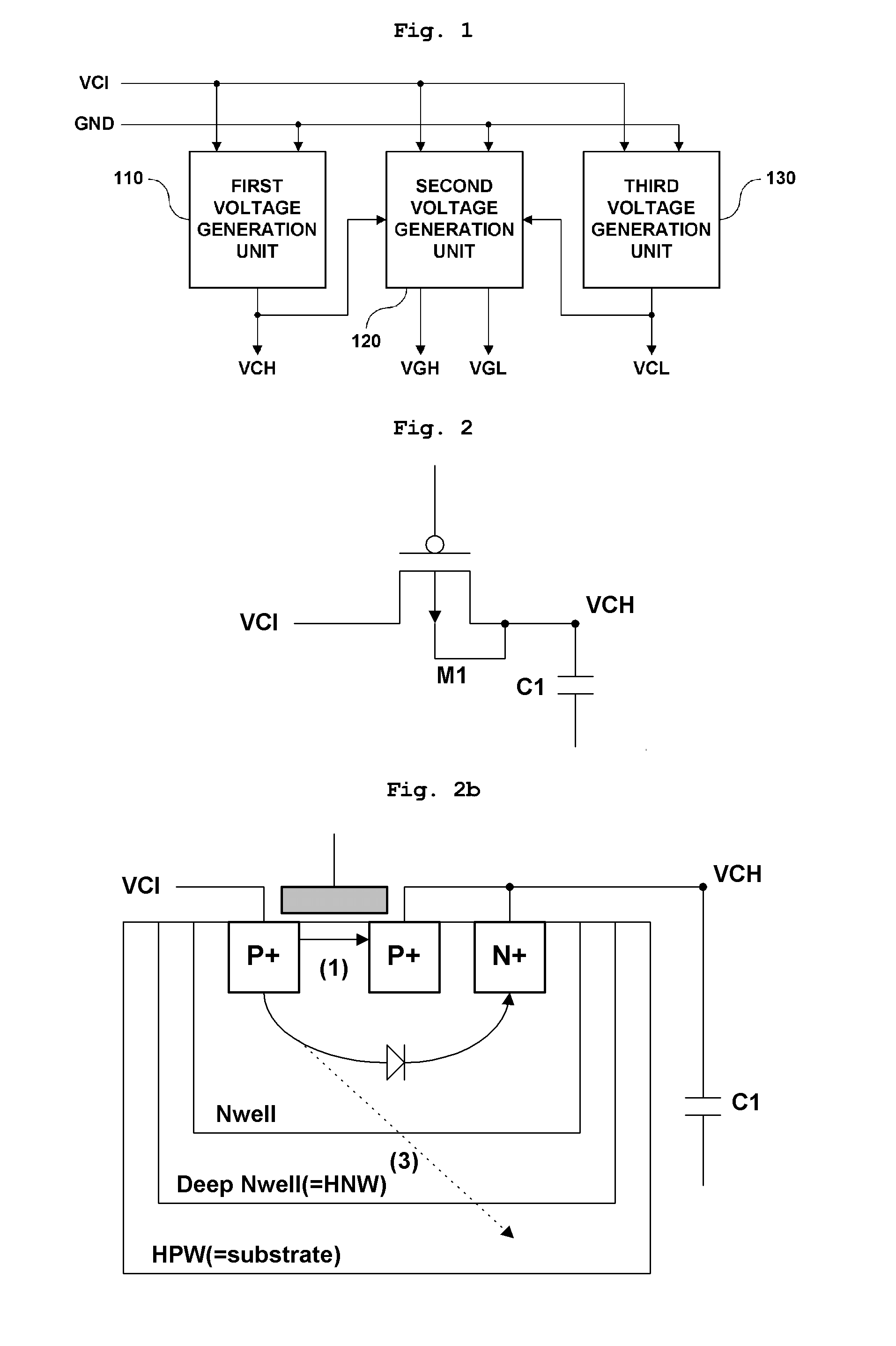
However, since excessive current is generated at the time of initially applying the input voltage VCI, there is a problem in that latch-up occurs.
However, there is a problem in that, when the voltage of the lower portion of the substrate increases along the path (3), as described above, the second driving voltage VGL has a predetermined magnitude before it is output, and thus latch-up occurs.
In this case, there is a problem in that the second driving voltage VGL is output early, out of sequence of the generation thereof, due to the through current generated along the path (1), and thus latch-up occurs.
However, there is a problem in that, since the Schottky diode 240 is separately manufactured, without being manufactured together with a display driving circuit, at the time of manufacturing the display driving circuit, and is attached to the display driving circuit, the costs increase in proportion to the cost of the materials for the Schottky diode 240.
Further, there is a problem in that, since a space corresponding to the size of the Schottky diode 240 is required in order to attach the Schottky diode to the display driving circuit, the size of the display driving circuit increases in proportion to the size of the Schottky diode 240.

Method used


Image

  • Display driving circuit
  • Display driving circuit
  • Display driving circuit

Examples


embodiment 1

[0050]FIG. 7 is a block diagram showing a first embodiment of the latch-up prevention unit 340 of the display driving circuit according to the present invention.

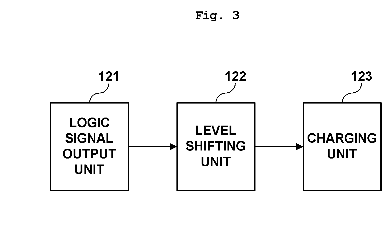
[0051]As shown in FIG. 7, the latch-up prevention unit 340 of the display driving circuit according to the present invention includes a control logic unit 341, a level shifting unit 342 and a switching means M0.

[0052]The control logic unit 341 is connected to the level shifting unit 342 and is configured to generate a control signal C, required to control the supply of the second driving voltage VGL, which is the lower of the first and second driving voltages VGH and VGL output from the second voltage generation unit 320 and is required to turn off the display panel, and to output the control signal C.

[0053]The level shifting unit 342 is connected both to the control logic unit 341 and to the switching means M0, and is configured to receive the control signal C, output from the control logic unit 341, and to output a gate vo...

embodiment 2

[0059]FIG. 8 is a block diagram showing a second embodiment of the latch-up prevention unit of the display driving circuit according to the present invention.

[0060]As shown in FIG. 8, the latch-up prevention unit 340 according to the second embodiment of the present invention includes a control logic unit 343, a decoding unit 344, a level shifting unit 345, and a switching unit 346.

[0061]In this case, the control logic unit 343 is connected both to the decoding unit 344 and to the level shifting unit 345, and is configured to generate a control signal C, required to control the supply of a second driving voltage VGL, which is the lower of the first and second driving voltages VGH and VGL output from the second voltage generation unit 320 and is required to turn off the display panel, and to transmit the control signal C to the decoding unit 344 and the level shifting unit 345.

[0062]The decoding unit 344 is connected to the control logic unit 343 and the level shifting unit 345, and ...


PUM


Abstract

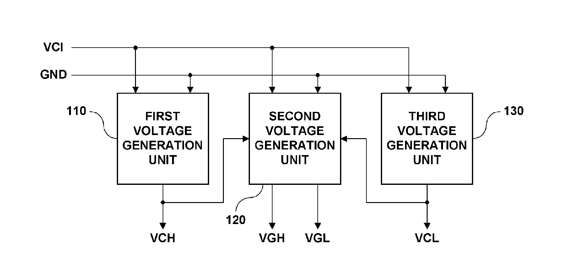
The present invention relates to a display driving circuit, which includes a latch-up prevention unit, thus preventing the occurrence of latch-up. The display driving circuit according to the present invention includes first to third voltage generation units configured to receive an externally applied input voltage having a same magnitude and generate respective voltages having different magnitudes, and a latch-up prevention unit connected to the second voltage generation unit and configured to receive a lower voltage among voltages output from the second voltage generation unit and to ground the lower voltage for a preset period of time. Accordingly, the second driving voltage output from the second voltage generation unit is connected to the latch-up prevention unit, including a plurality of switching means connected to the ground, and is grounded for a preset period of time, thus preventing the occurrence of latch-up and reducing the size of the driving circuit.

Description

CROSS-REFERENCE TO RELATED APPLICATION[0001]The benefit of priority is claimed to Republic of Korea patent application no. 10-2007-0065343, filed Jun. 29, 2007, which is incorporated by reference herein in its entirety.BACKGROUND[0002]1. Field of the Invention[0003]The present invention relates, in general, to a display driving circuit for preventing latch-up, and, more particularly, to a display driving circuit, in which a second driving voltage output from a second voltage generation unit is connected to a latch-up prevention unit composed of a plurality of switching means and is grounded for a preset period of time, thus preventing the occurrence of latch-up.[0004]2. Description of the Related Art[0005]Generally, a Liquid Crystal Display (LCD) is an electric device for converting various types of electrical information, generated by various devices, into visual information using variation in the transmissivity of liquid crystal depending on an applied voltage, and for transmittin...

Claims


Application Information

Patent Timeline
Patent Type & Authority Applications(United States)
IPC IPC(8): G06F3/038
CPCH01L27/0248G09G3/3696G02F1/133G09G3/20G09G3/36H02H7/12
Inventor KANG, TAE KYOUNGMYOUNG, JUN HYOUNGKIM, JIN WOOK
Owner MAGNACHIP SEMICONDUCTOR LTD
Learn More