Network management apparatus and switching apparatus

a network management and switching device technology, applied in electrical devices, data switching networks, digital transmission, etc., can solve the problems of not being able to acquire all the information needed for communication with other switching devices, unable to automatically mean communication, and unable to acquire mac addresses

Inactive Publication Date: 2008-08-07
ALAXALA NETWORKS
View PDF4 Cites 100 Cited by
  • Summary
  • Abstract
  • Description
  • Claims
  • Application Information

AI Technical Summary

Benefits of technology

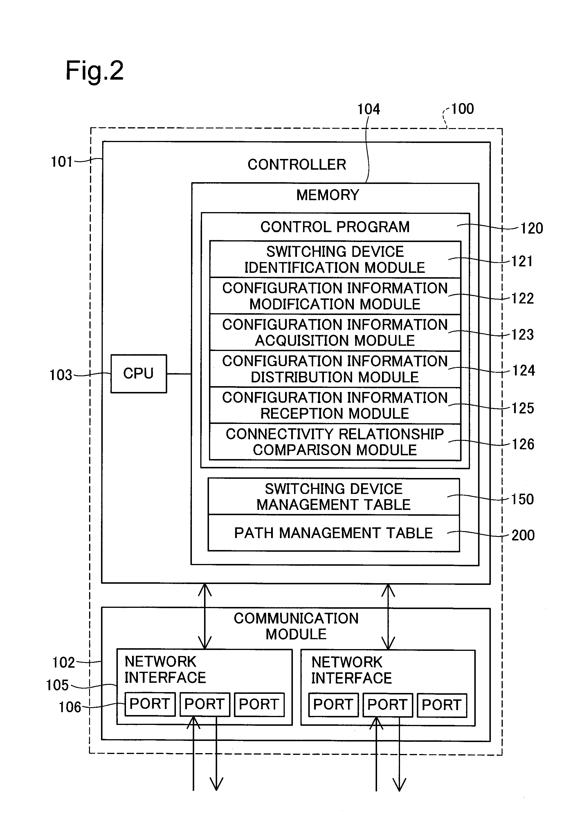
[0018]According to the network management apparatus pertaining to the first aspect, a change in connectivity among switching devices will be detected, and the configuration information managed in the network management apparatus will be modified dynamically in response to the detected change. Thus, by setting the modified configuration information in the switching devices, disabling of communication among switching devices under management may be prevented or largely avoided.
[0031]The switching device pertaining to the second aspect may further comprises an address acquirer. The address acquirer may acquire an address externally so that the communication module is communicatable with the network management apparatus, in the event that the communication module is not communicatable with the network management apparatus. In this case, even in the event that a switching device is not communicatable with the network management device at a specific address, it will nevertheless be able to acquire another address externally and communicate with the network management device. As a result, the likelihood of switching devices being able to maintain communication with the network management device may be improved.

Problems solved by technology

DHCP (Dynamic Host Configuration Protocol) is one means for acquiring and setting external IP addresses for the purpose of enabling communications; however, DHCP can only acquire IP addresses, and cannot acquire all of the information needed for communication with other switching devices.
Many switching devices have an automatic learning function for learning the MAC addresses for use in communications by Ethernet™; however, owing to existence of VLAN (Virtual Local Area Network) or other technologies for logical division of communications, learning MAC addresses does not automatically mean that communication is possible.
Thus, using broadcast packets, a switching device belonging to a first VLAN will not be able to communicate with a switching device belonging to a second VLAN.
ARP has the same problem described above, since it involves saving associations among IP addresses and MAC addresses, and using the IP address to ascertain the MAC address belonging to a device.
That is, even where a switching device uses ARP, if the configuration information of the switching device is not correct, it will not be able to communicate with a device belonging to a different VLAN, despite learning its MAC address.
If configuration information in switching devices, such as addresses or identifiers of paired switching devices, have been made in error, communication among switching devices will not be possible.
However, while it is possible to make configuration information appropriately in the two switching devices by using correct path information, in the event that the path information is in error, it will of course not be possible to set appropriate configuration information.
Moreover, it is difficult to obtain correct path information from configuration information for the two switching devices.
1. the actual physical wiring of network cables or optical fibers may not have been wired correctly as designed; and
2. since switching devices are designed for distributed autonomous operation, it is possible that through direct login to a switching device its configuration may have been changed without regard to paired network devices or to physical wiring. Thus, the configuration information will not necessarily be correct.
Consequently, even if the configuration information includes description of “communications ports of paired devices” and so on, such configuration information may not be reliable for the purpose of creating path information.
However, by so doing it will no longer be possible to perform a restore operation on a switching device in the event that it can no longer communicate with the management device; therefore, such changes to configuration information through direct login must be permitted.
While it would be conceivable to allow changes to be made to configuration information through direct login only in those exceptional instances where communication with the management device is not possible, and to enable configuration to be made only from the management device at other times, this is not really a solution, since the same problem will be confronted when communication with the management device becomes possible.

Method used


Image

  • Network management apparatus and switching apparatus
  • Network management apparatus and switching apparatus
  • Network management apparatus and switching apparatus

Examples


embodiment 1

c-1) Specific Embodiment 1

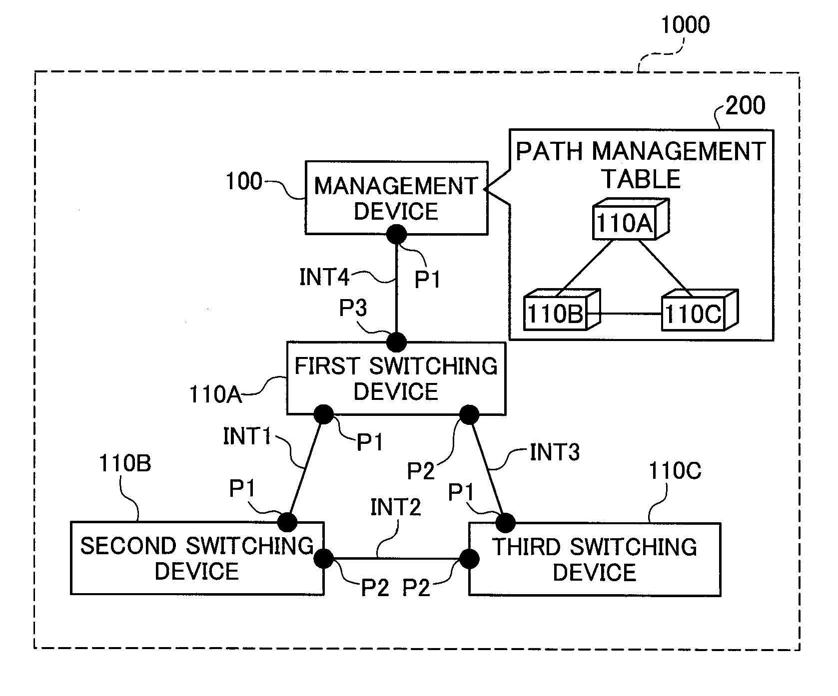
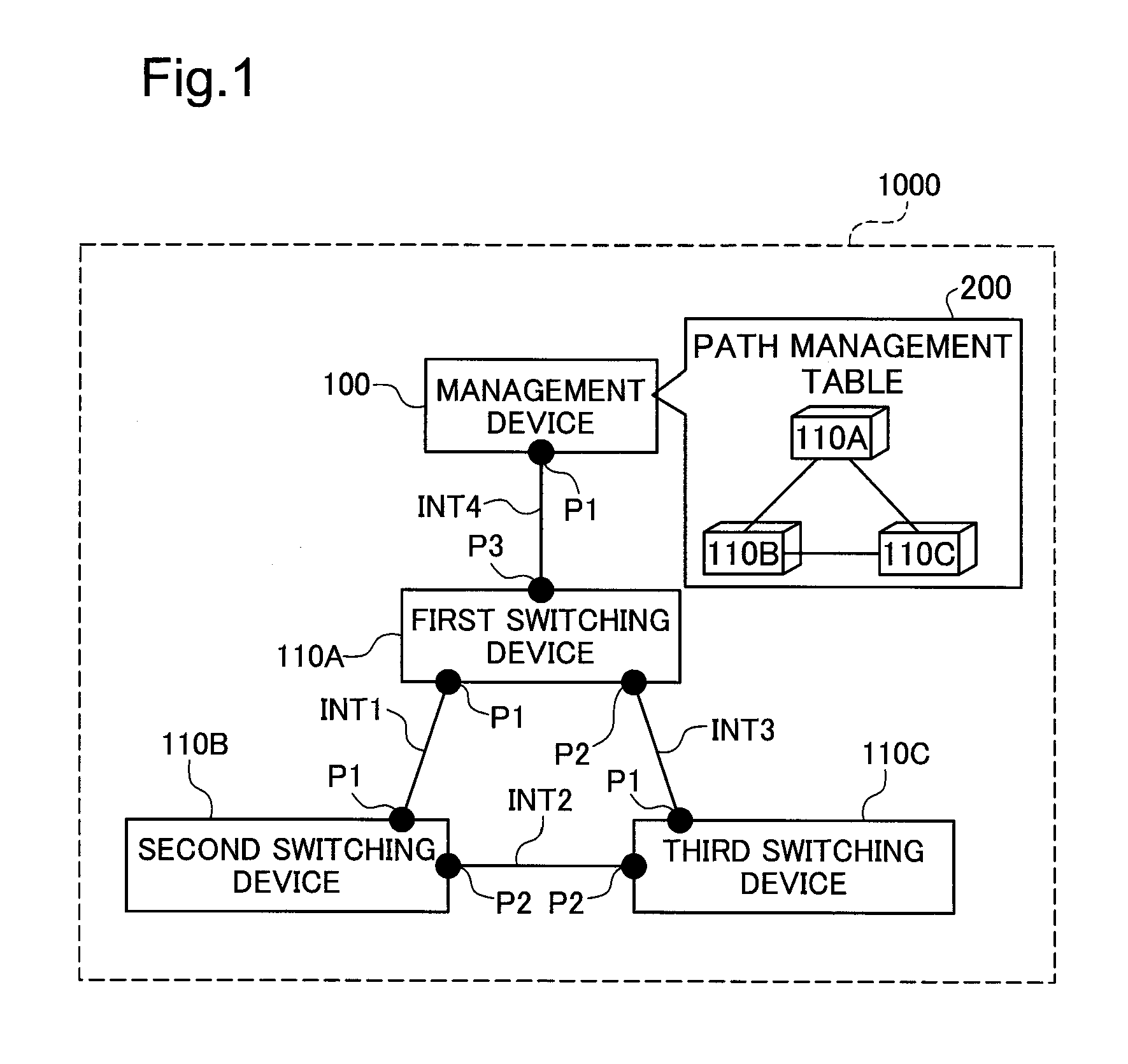
[0135]One specific embodiment of operation of the Network System 1000 discussed above will be described with reference to FIGS. 16 through 20. This specific embodiment shall describe processes taking place from a state in which the first switching device 110A is operating normally and the third switching device 110C is stopped, to a state in which the third switching device 110C is booted up and becomes operational. FIG. 16 is a sequence diagram showing the processing sequence of the Network System in Specific Embodiment 1. FIG. 17 is an illustration depicting an example of configuration information that is configured in the third switching device when the third switching device is booted up in Specific Embodiment 1. In FIG. 17, an example of the port-related information in the configuration information 160 of the third switching device 110C is shown. FIG. 18 is an illustration depicting an example of configuration information that is configured in the firs...

embodiment 2

c-2) Specific Embodiment 2

[0162]One specific embodiment of operation of the Network System 1000 discussed above will be described with reference to FIG. 21. This specific embodiment shall describe the processes in the event that for some reason the third switching device 110C has stopped. FIG. 21 is a sequence diagram depicting the Network System in Specific Embodiment 2.

[0163]Once the third switching device 110C stops (P10), the third switching device 110C will no longer be able to transmit verification of live communication to the management device 100, and will no longer be able to transmit verification of live communication to the other switching devices 110.

[0164]Once the verification of live communication that was periodically transmitted from the third switching device 110C has ceased (FIG. 21: C10), the management device 100 will detect this (FIG. 12: S430: YES), and will change the value of the communication status 155 with the third switching device 110C in the switching d...

embodiment 3

c-3) Specific Embodiment 3

[0168]One specific embodiment of operation of the Network System 1000 discussed above will be described with reference to FIG. 22. This specific embodiment shall describe the processes in the event that, despite the third switching device 110C having been booted up, it cannot communicate with the management device 100 for some reason. FIG. 22 is a sequence diagram depicting the Network System in Specific Embodiment 3.

[0169]If a communication failure has occurred so that communication is not possible between the third switching device 110C and the management device 100 (FIG. 22: P10, PL20), communication can no longer be established between the third switching device 110C and the management device 100, and verification of live connection can no longer be transmitted to the management device 100.

[0170]Once the verification of live communication that was periodically transmitted from the third switching device 110C has ceased (FIG. 22: C10), the management dev...


PUM


Abstract

A network management apparatus is for managing a plurality of switching devices that relay data through a data communication network. The network management apparatus includes a configuration information storage, a connectivity relationship detector and a configuration information modifier. The configuration information storage stores first configuration information. The first configuration information is configured in the switching devices and includes information to be determined in accordance with connectivity relationships among the switching devices. The connectivity relationship detector detects changes of connectivity relationships among the switching devices. The configuration information modifier dynamically modifies the first configuration information in accordance with detected changes of connectivity relationships.

Description

CROSS REFERENCE TO RELATED APPLICATIONS[0001]This application relates to and claims priority from Japanese Patent Applications No. 2007-22928, filed on Feb. 1, 2007, the entire disclosure of which is incorporated by reference.BACKGROUND[0002]1. Technical Field[0003]The present invention relates to technology for managing a switching device in network operation.[0004]2. Description of the Related Art[0005]Currently available switching devices have been designed on the assumption that they will be operated in distributed autonomous mode. This is because switching devices are the devices that provide communication accessibility, and because the transfer functionality of a switching device must not come to a stop even if communication with the server managing the switching device should be interrupted. For this reason, switching devices are not designed to operate according to instructions from other devices, but instead to operate based on internal configuration information made in the...

Claims


Application Information

Patent Timeline
Patent Type & Authority Applications(United States)
IPC IPC(8): H04L12/28H04L45/28
CPCH04L41/0816H04L49/65H04L49/555H04L43/0811
Inventor KITANI, MAKOTO
Owner ALAXALA NETWORKS
Why Eureka
Try Eureka