Image forming apparatus and image forming method thereof

Inactive Publication Date: 2008-08-07
HEWLETT PACKARD DEV CO LP
View PDF9 Cites 3 Cited by
  • Summary
  • Abstract
  • Description
  • Claims
  • Application Information

AI Technical Summary

Benefits of technology

[0013]The present general inventive concept provides an image forming appar

Problems solved by technology

The potential difference between the rear end contact surface C and the photosensitive drum 40 having −800V surface potential is continuously maintained to cause poor picture

Method used


Image

  • Image forming apparatus and image forming method thereof
  • Image forming apparatus and image forming method thereof
  • Image forming apparatus and image forming method thereof

Examples


Embodiment Construction

[0054]Reference will now be made in detail to the embodiments of the present general inventive concept, examples of which are illustrated in the accompanying drawings, wherein like reference numerals refer to the like elements throughout. The embodiments are described below in order to explain the present general inventive concept by referring to the figures.

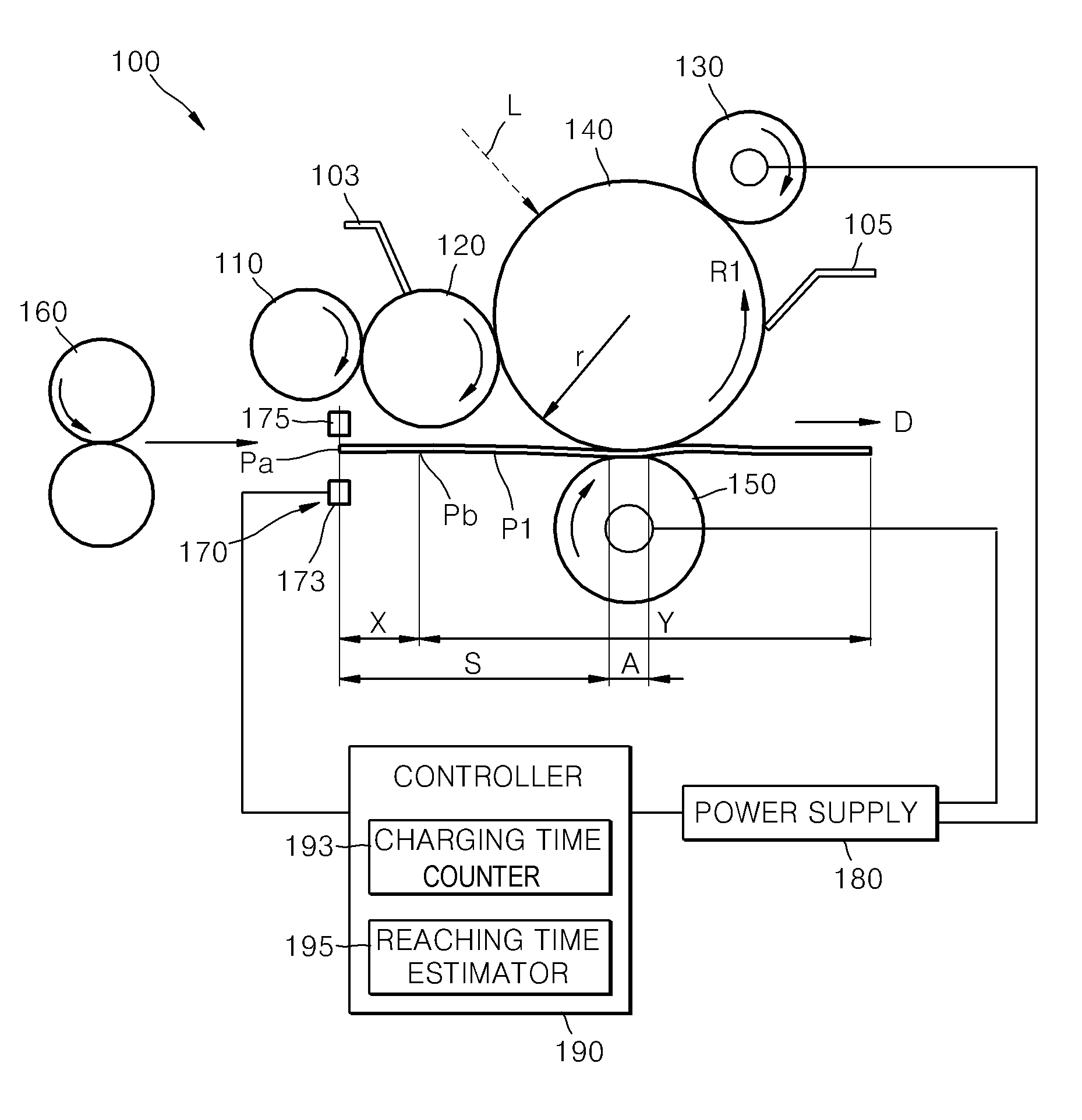
[0055]FIG. 2A illustrates an image forming apparatus 100 right after a rear end Pa of a printing medium P1 passes a first medium detector 170. FIG. 2B illustrate the image forming apparatus 100 when the printing medium P1 in FIG. 2A has moved in a paper-feeding direction and a start point Pb of a non-printing section X of the printing medium P1 in FIG. 2B starts to pass a transfer region A. FIG. 2C illustrate the image forming apparatus 100 when the rear end Pa of the printing medium P1 starts to leave the transfer region A and move away from a photosensitive body 140.

[0056]The printing medium P1 has a printing section Y and a n...


PUM


Abstract

An image forming apparatus includes a photosensitive body to be developed by a conductive toner, a charger which charges a surface of the photosensitive body with a surface potential, a power supply which supplies one of a normal charging power to perform a normal charging operation and a compensation charging power, having a different absolute value than the normal charging power and having the same polarity as the normal charging power, to the charger, and a controller which controls the power supply to supply the normal charging power and the compensation charging power to the charger, respectively, before and after a charging time at which a rear end contact surface of the photosensitive body contacting a rear end of a printing medium is charged by the charger.

Description

CROSS-REFERENCE TO RELATED APPLICATIONS[0001]This application claims priority under 35 U.S.C. §119(a) from Korean Patent Application No. 10-2007-0011072, filed on Feb. 2, 2007, in the Korean Intellectual Property Office, the disclosure of which is incorporated herein in its entirety by reference.BACKGROUND OF THE INVENTION[0002]1. Field of the Invention[0003]The present general inventive concept relates to an image forming apparatus and an image forming method thereof, and more particularly, to an image forming apparatus which improves a printing quality, and an image forming method thereof.[0004]2. Description of the Related Art[0005]An electrophotograhic image forming apparatus forms an image on a printing medium through charging, exposing, developing, transferring and fixing processes. The electrophotograhic image forming apparatus includes a laser printer, a photocopier, a multifunction printer, etc.[0006]As illustrated in FIGS. 1A and 1B, a conventional electrophotograhic image...

Claims


Application Information

Patent Timeline
IPC IPC(8): G03G15/00
CPCG03G2215/00573G03G15/0266G03G15/1675G03G15/5037G03G15/0225G03G2215/021
Inventor KWON, TAI-EUN
Owner HEWLETT PACKARD DEV CO LP
Why Eureka
Try Eureka