Thorascopic Heart Valve Repair Method and Apparatus

a heart valve and thoracic valve technology, applied in the direction of surgical forceps, instruments, catheters, etc., can solve the problems of prolonged hospital stay, high trauma degree, and significant risk of complications

Active Publication Date: 2008-08-07
MAYO FOUND FOR MEDICAL EDUCATION & RES
View PDF85 Cites 104 Cited by
  • Summary
  • Abstract
  • Description
  • Claims
  • Application Information

AI Technical Summary

Benefits of technology

The invention is a tool and technique that allows heart valves to be repaired without needing to open the chest and stop the heart. The tool is inserted through a small incision in the chest wall and into the heart chamber while the heart is still beating. This tool can repair a heart valve and then be withdrawn from the heart and chest.

Problems solved by technology

The technical problem addressed in this patent text is the need for improved surgical procedures to repair and replace heart valves without the need for a gross thoracotomy and cardiopulmonary bypass with aortic cross-clamp and cardioplegic arrest of the heart. Current techniques require a sternotomy and involve a high degree of trauma and risk of complications. The patent text describes various techniques and methods for accessing and repairing heart valves, including mitral and tricuspid valves, as well as the subvalvular apparatus.

Method used


Image

  • Thorascopic Heart Valve Repair Method and Apparatus
  • Thorascopic Heart Valve Repair Method and Apparatus
  • Thorascopic Heart Valve Repair Method and Apparatus

Examples


second embodiment

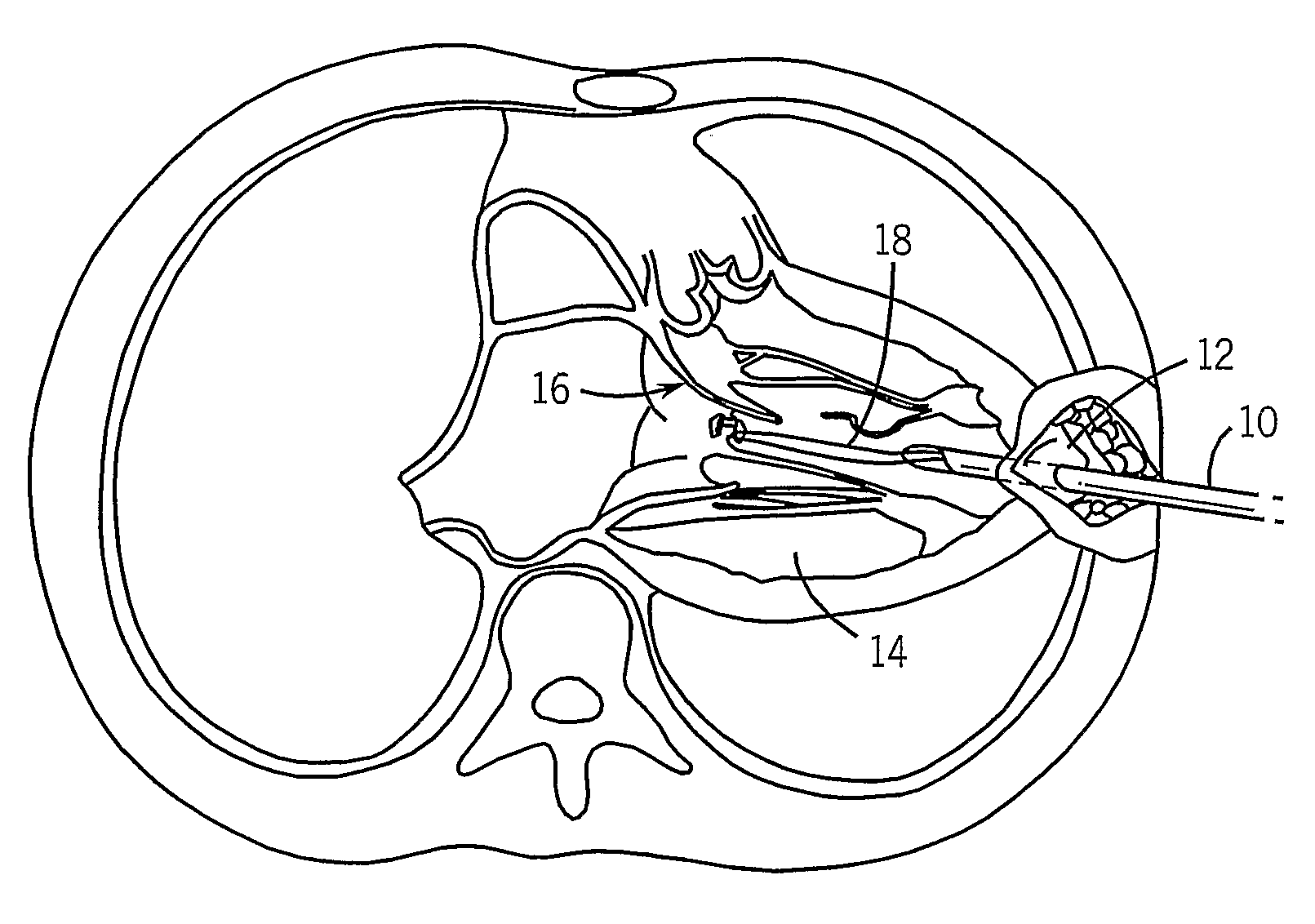
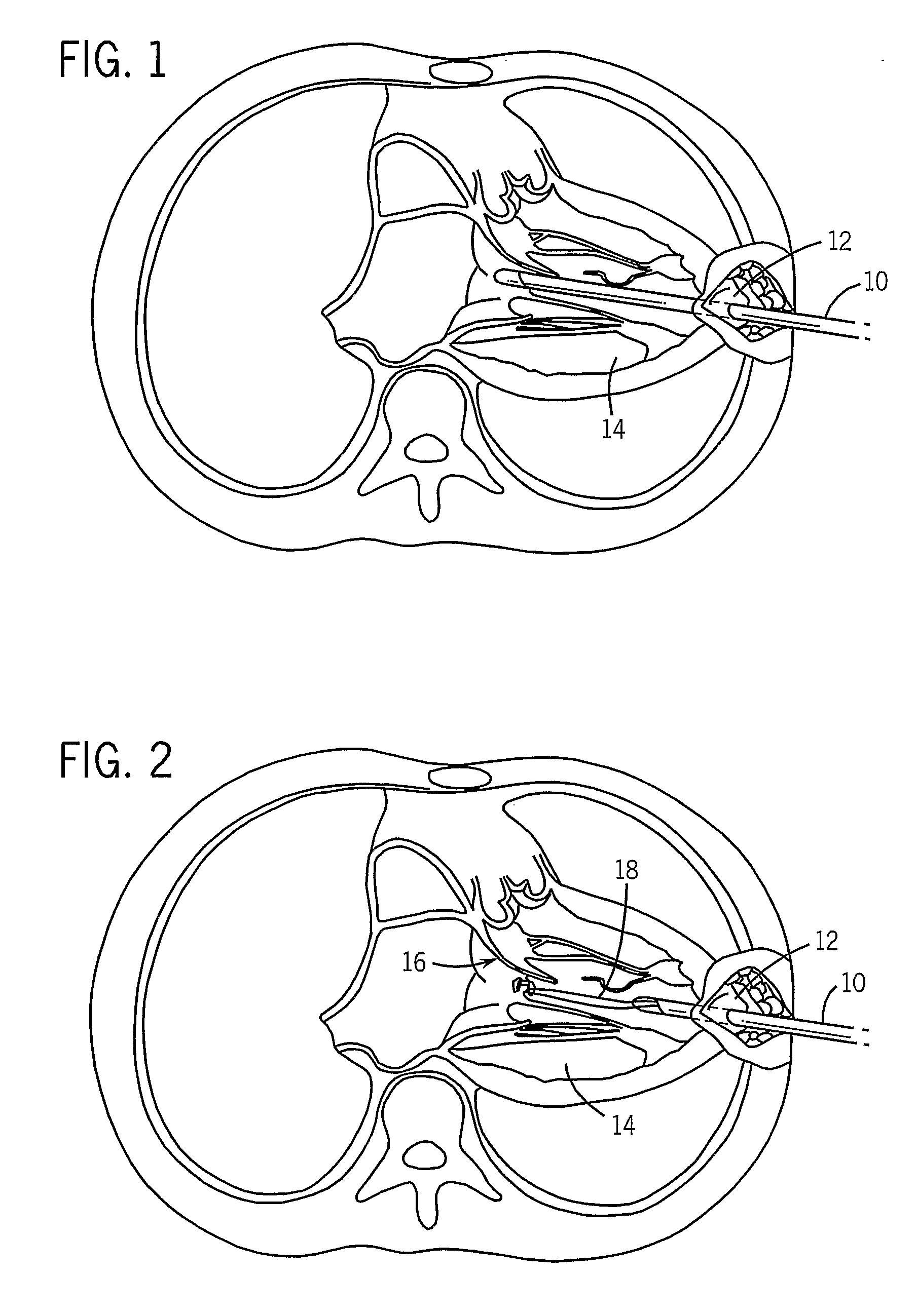
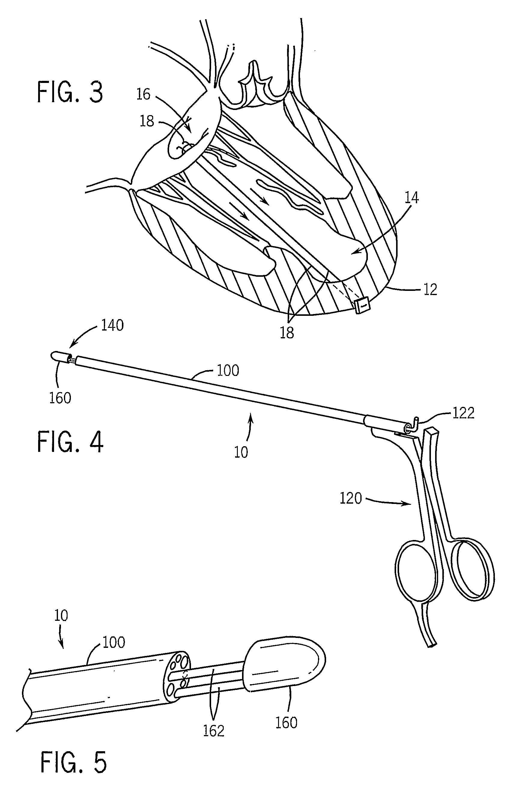
[0024]As shown in FIGS. 9A-9D, the suture deployment system at the distal end of the instrument 10 is positioned around a valve leaflet 16 to be repaired as shown in FIG. 9A. The suture 18 in this embodiment is a closed loop with one end of the loop disposed in the tip 160 and its other end disposed in the lumen 164 and wrapped around the needle 180. The needle 180 is extended through the grasped valve leaflet 16 into the instrument tip 160 where it hooks one end of the looped suture 18 in a notch 166 formed on one side of the needle as shown in FIG. 9B. The needle 180 is then retracted to pull the the looped suture 18 through the puncture opening in the leaflet 16. The leaflet is then released as shown in FIG. 9C by sliding the tip 160 to its open position. The instrument 10 is then withdrawn as shown in FIG. 9D to slide the unhooked end of the looped suture 18 along the length of the needle toward the leaflet 16 where it forms a Larks head around the leaflet edge.

[0025]The instrum...

third embodiment

[0026]As shown in FIGS. 10A-10D, the suture deployment system at the distal end of the instrument 10 is positioned around a valve leaflet 16 to be repaired as shown in FIG. 10A. The midpoint 17 of the suture 18 is looped around the lumen 164 and its two loose ends 20 are coiled up in the tip 160. After the tip 160 is closed to capture the valve leaflet 16, the needle 180 is extended through the grasped valve leaflet 16 into the instrument tip 160. The free ends 20 of the suture 18 are positioned in the tip 160 to form a loop 19 and a notch 166 formed on one side of the needle extends through this loop 19 and “hooks” the free ends of the suture 18 as shown in FIG. 10B. The needle 180 is then retracted back into the lumen 164 to pull the hooked ends of the suture 18 through the puncture opening in the leaflet 16. The leaflet is then released as shown in FIG. 10C by sliding the tip 160 to its open position. The instrument 10 is then withdrawn from the heart as shown in FIG. 10D to pull...


PUM


Abstract

An instrument for performing thorascopic repair of heart valves includes a shaft for extending through the chest cavity and into a heart chamber providing access to a valve needing repair. A movable tip on the shaft is operable to capture a valve leaflet and a needle is operable to penetrate a capture valve leaflet and draw the suture therethrough. The suture is thus fastened to the valve leaflet and the instrument is withdrawn from the heart chamber transporting the suture outside the heart chamber. The suture is anchored to the heart wall with proper tension as determined by observing valve operation with an ultrasonic imaging system.

Description


Claims


Application Information

Patent Timeline
Owner MAYO FOUND FOR MEDICAL EDUCATION & RES
Why Eureka
Try Eureka