Portable construction staircase

a construction staircase and portability technology, applied in the direction of construction, building parts, building construction, etc., can solve the problems of difficult transportation, large volume, and limited choice of prior art temporary staircases, and achieve the effect of convenient transportation and convenient transportation

Inactive Publication Date: 2008-08-14
MUTI DAVID
View PDF34 Cites 13 Cited by
  • Summary
  • Abstract
  • Description
  • Claims
  • Application Information

AI Technical Summary

Benefits of technology

[0006]The present invention is a portable staircase for use at construction sites that comprises fold-down railings to facilitate transport from one construction site to the next. The portable staircase includes a plurality of horizontal treads supported by stringers. At least one handrail is provided which is pivotally connected to the stringer utilizing a plurality of handrail support posts. A permanent pivot pin pivotally connects the handrail to each of the handrail support posts. Another permanent pivot pin pivotally connects each of the handrail support posts to the stringer. The handrail can be locked into one of two pre-selected positions: a first folded-down position to facilitate transportation and a second upright position for use at construction sites. The stringer, handrail posts and handrail are all predrilled with pin-receiving holes in order to lock the handrail in its chosen position utilizing a removable pin. If desired, two removable pins may be employed to lock the handrail in position: a first removable pin to lock the handrail support post to the stringer and a second removable pin to lock the handrail support post to the handrail in the up and usable position.

Problems solved by technology

These contractors, homeowners, designers and inspectors do not like or feel safe climbing these ladders, but they have little choice until the permanent stairs are installed.
These prior art temporary staircases are typically extremely heavy, and more importantly, bulky.
As such, they are difficult to transport, and virtually impossible for a contractor to relocate from one job site to the next.

Method used


Image

  • Portable construction staircase
  • Portable construction staircase
  • Portable construction staircase

Examples


Embodiment Construction

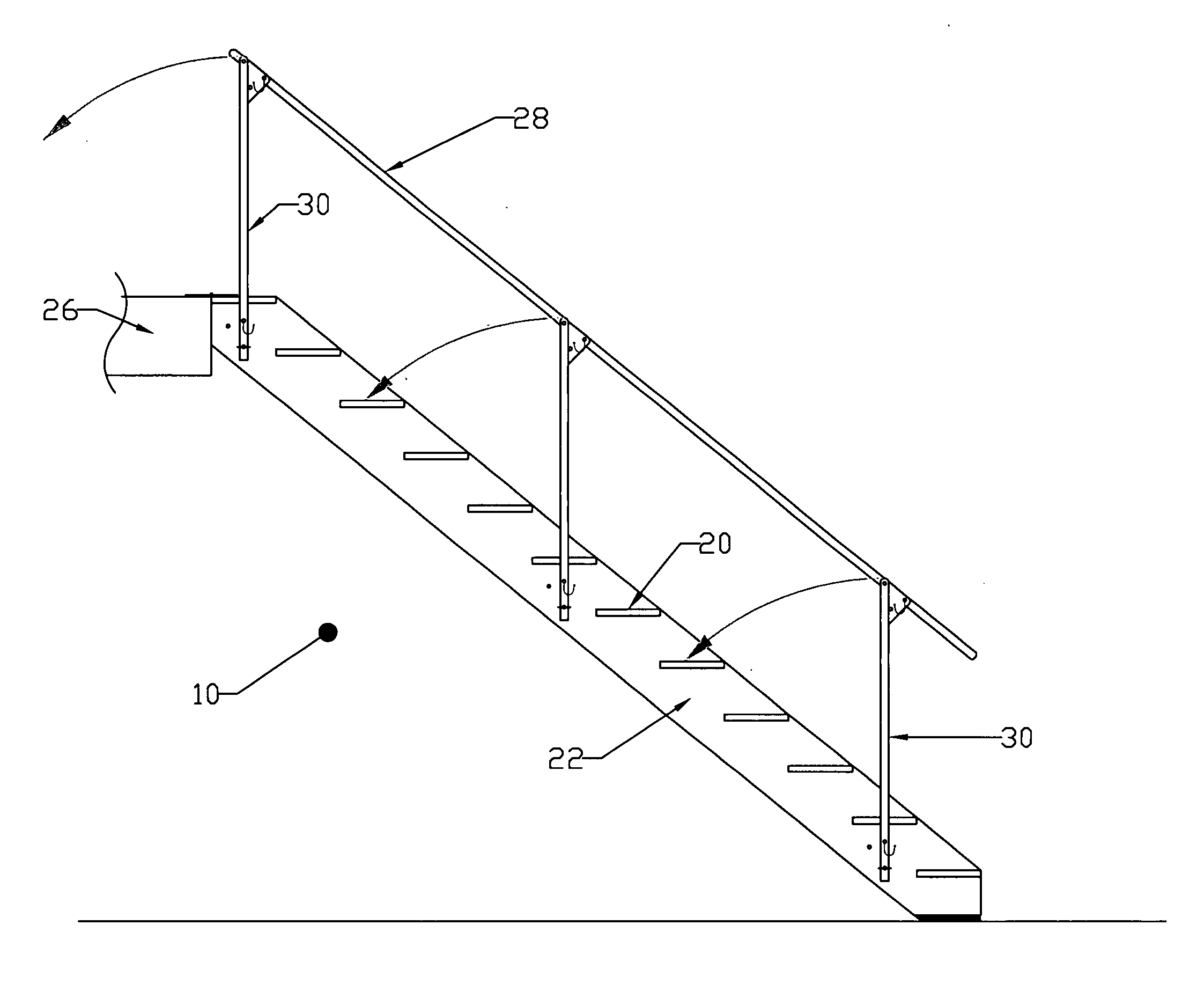
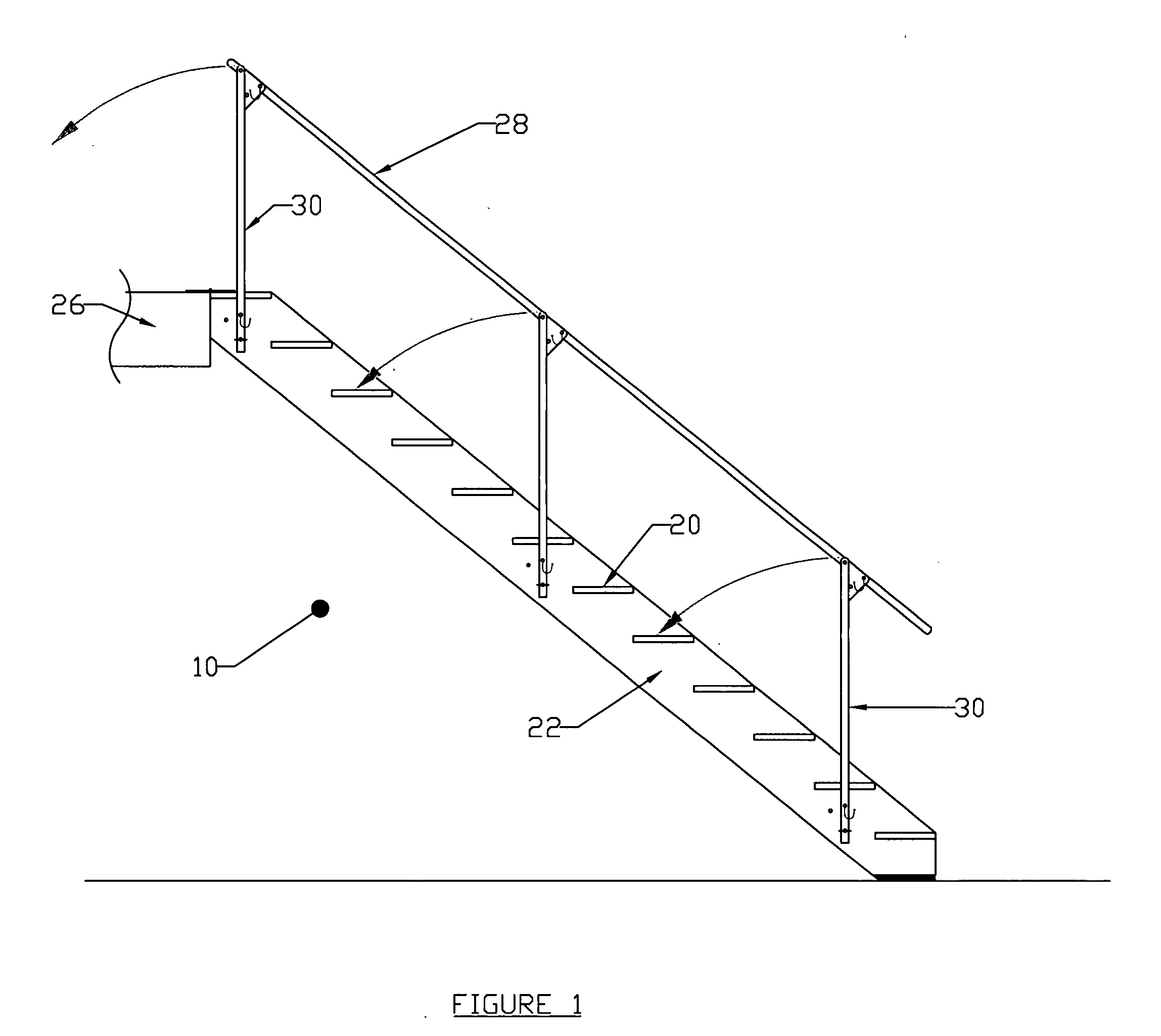
[0015]Referring to the figures, the present invention is a portable temporary staircase 10 for use at construction sites or the like. The temporary staircase of the present invention includes a fold-down railing so that the staircase unit can more readily be transported from one job site to the next.

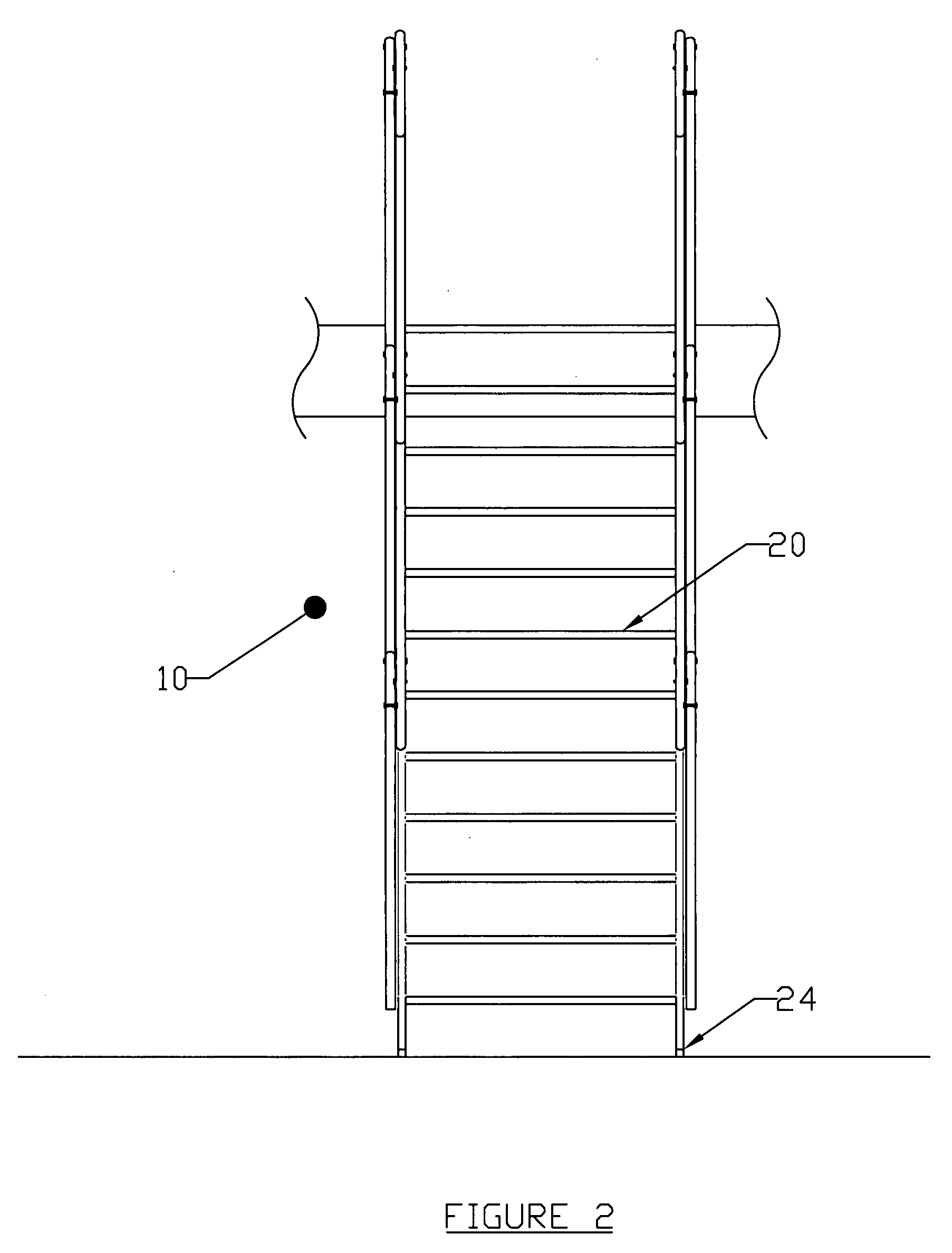
[0016]The construction staircase of the present invention includes a plurality of horizontal tread members 20 supported by a plurality of stringers 22 each step typically having a standard 8″ rise and 10″ run. The width of each horizontal tread member is typically 30″ although staircases having other dimensions are within the scope of this disclosure. The horizontal tread members are formed as a honeycomb to provide improved traction and to reduce transportation weight. The staircase is installed to run from the lower deck (floor) 24 to the floor joist of the next deck 26 and is nailed in place by adjustable flanges to the upper deck floor joist. At the bottom of stringers are attached v...


PUM


Abstract

A portable staircase for use at construction sites that comprises fold-down railings to facilitate transport from one construction site to the next. The portable staircase includes a plurality of horizontal treads supported by stringers. Handrails are provided which pivotally connect to the stringer utilizing a plurality of handrail support posts. A permanent pivot pin pivotally connects the handrail to each of the handrail support posts. Another permanent pivot pin pivotally connects each of the handrail support posts to the stringer. The handrail can be locked into one of two pre-selected positions: a first folded-down position to facilitate transportation and a second upright position for use at construction sites. Two removable pins may be employed to lock the handrail in position: a first removable pin to lock the handrail support post to the stringer and a second removable pin to lock the handrail support post to the handrail in the up and usable position.

Description

FIELD OF THE INVENTION [0001]The present invention is a portable staircase for use at construction sites and more specifically a portable staircase which includes a hand railing which can be folded down to facilitate transportation.BACKGROUND OF THE INVENTION [0002]The present invention is a portable staircase that can be utilized by contractors or construction crews at construction sites. Many contractors that renovate homes and / or build new homes or other structures must climb ladders to go from one floor to the next during the construction phase. This method of ascending floors remains in place until either a temporary staircase is built or the permanent staircase is installed. These contractors, homeowners, designers and inspectors do not like or feel safe climbing these ladders, but they have little choice until the permanent stairs are installed.[0003]There are many prior art prefabricated staircases already on the market, but none of them address the portability issue that ha...

Claims


Application Information

Patent Timeline
Patent Type & Authority Applications(United States)
IPC IPC(8): E04F11/00
CPCE04G27/00
Inventor MUTI, DAVID
Owner MUTI DAVID
Why Eureka
Try Eureka