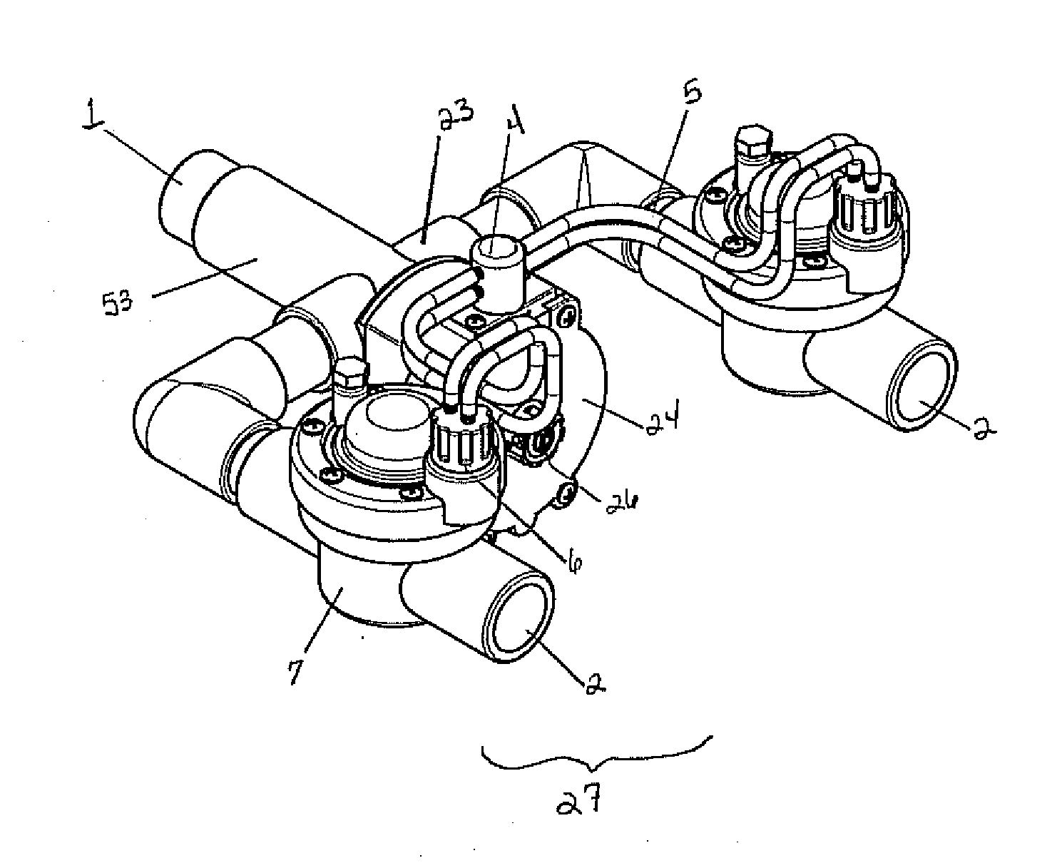
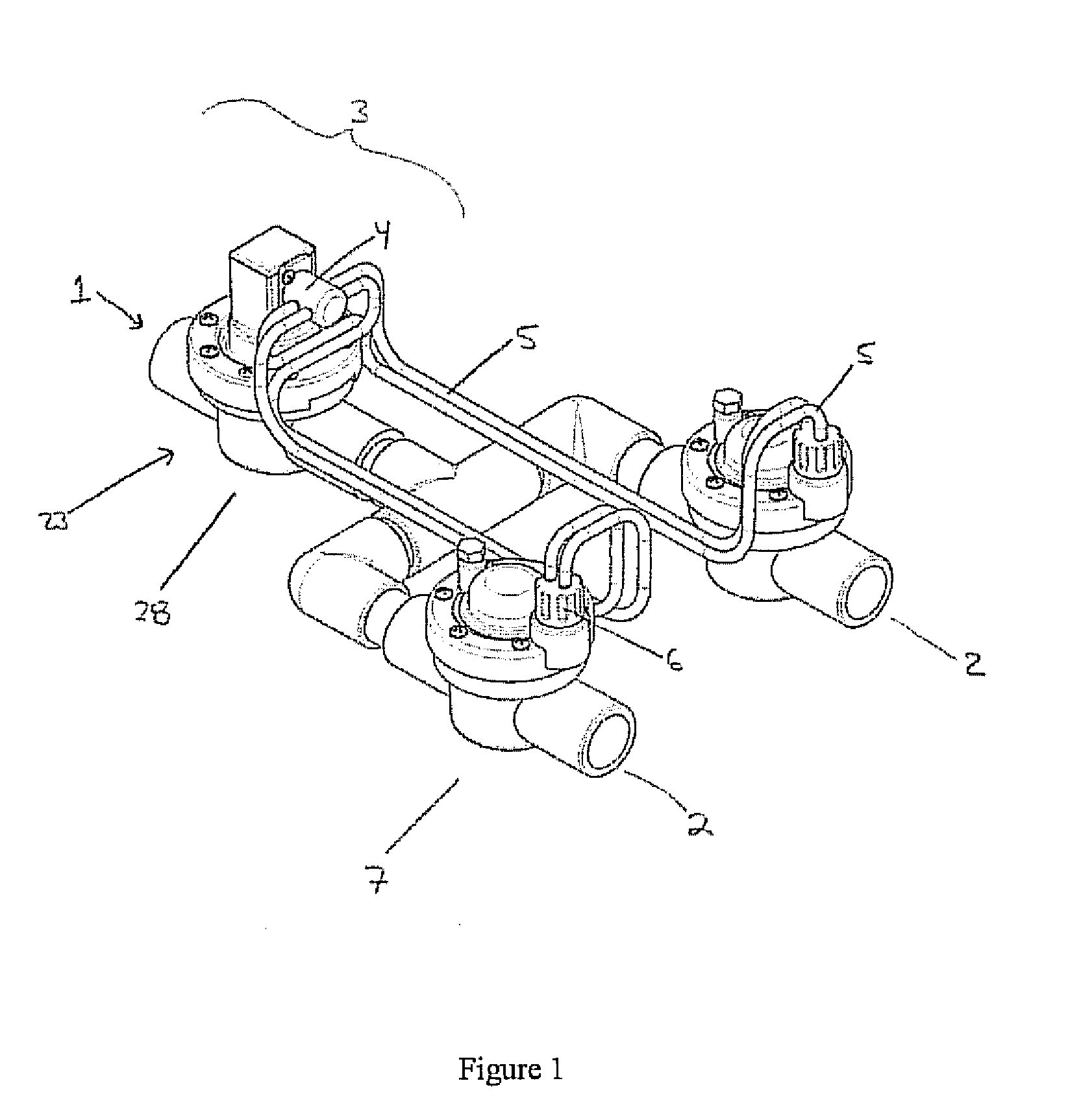
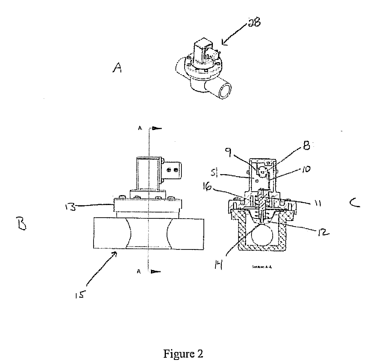
Fluid activated flow control system
a flow control system and fluid activation technology, applied in the direction of valve operating means/releasing devices, process and machine control, etc., can solve the problems of inability to expand the flow in the pipeline, the cost of adding new pipe runs is high, and the cost of trenching and cutting or circumventing the pavement is high
Inactive Publication Date: 2008-08-14
HURST JAMES W
View PDF24 Cites 13 Cited by
- Summary
- Abstract
- Description
- Claims
- Application Information
AI Technical Summary
Benefits of technology
[0017]The output valve is provided with a flow control
Problems solved by technology
Thus, for any single fluid source the flow in a pipeline is not expandable beyond a given length or number of fluid delivery terminals such as a sprinkler head.
Thus, expansion of fluid delivery coverage is difficult, costly, and commonly involves addition of additional source controls and pipe.
Adding new pipe runs has the added difficulty of requiring costly trenching and cutting or circumventing pavement such as sidewalls, roads, driveways, and patios.
More importantly, should all the control circuits be utilized in the existing system, expansion will require addition of a new or additional timing mechanism further increasing the cost, maintenance, and difficulty of operating the system.
This adds significantly to the cost of expanding an existing irrigation system and results in increased maintenance needs.
This multiple control system is costly to purchase and install.
Further, expansion of the existing system requires additional trenching to install new electric lines to regulate new valve systems.
These devices suffer from numerous drawbacks including water hammering due to slow activation or deactivation of the output valves and difficult or absent timing adjustment.
Devices that provided timing adjustment required a difficult and awkward process of changing the cams within the mechanism, thus requiring shutting down the system and professional adjustment.
Installation of prior art water distribution systems requires replacing or removing existing valve systems and replacing them with a complicated control device.
The complexity of the prior art control devices requires precise manufacturing standards to ensure functionality and results in increased cost of purchase, operation, and maintenance, thus, increasing warranty replacement costs and detrimentally affecting customer goodwill.
Method used
View moreImage
Smart ImageViewing Examples
Examples
example 1
[0088]Operation: Referring to FIG. 10, a fluid activated servo assembly equipped with a self-activating servo assembly has been tested and performs the desired tasks reliably and efficiently. The figures demonstrate the device operating with water exiting through either output port and spraying out of nozzles that simulate normal sprinkler head pressure losses. One full cycle of watering through both ports is approximately 10 minutes.
Login to View More PUM
 Abstract
A fluid flow regulating device is provided that maintains pressure and flow rate characteristics of a source fluid while the fluid is distributed to multiple delivery lines. The inventive device switches between multiple output ports in response to fluid pressure changes or by a mechanism driven by fluid flow. Thus, existing fluid delivery systems are easily expandable while avoiding installation of additional timing control mechanisms, electrical runs, or fluid sources.
Description
CROSS-REFERENCE TO RELATED APPLICATIONS[0001]This application claims the benefit of U.S. Provisional Application No. 60 / 901,055 filed Feb. 12, 2007, which is incorporated herein by reference.FIELD OF THE INVENTION[0002]This invention relates generally to devices for regulating fluid flow. More specifically, the instant invention relates to a system for regulating fluid flow between one or more lines. More specifically, the instant invention relates to a pressure or automatic fluid activated flow control system suitable for regulating fluid flow between one or more fluid delivery lines suitable for use in irrigation.BACKGROUND OF TEE INVENTION[0003]Agricultural, commercial, and domestic irrigation systems are commonly constructed of fixed piping that depend on a single source for delivery of water to the entire system. The flow in a given pipeline is limited by its length, diameter, internal surface condition, and fluid pressure. Thus, for any single fluid source the flow in a pipeli...
Claims
Login to View More Application Information
Patent Timeline
 IPC IPC(8): F16K11/00
CPCF16K11/22G05D7/0664F16K31/04Y10T137/268Y10T137/2693Y10T137/86582
Inventor HURST, JAMES W.
Owner HURST JAMES W
Features
- R&D
- Intellectual Property
- Life Sciences
- Materials
- Tech Scout
- Unparalleled Data Quality
- Higher Quality Content
- 60% Fewer Hallucinations
Learn More Browse by: Latest US Patents, China's latest patents, Technical Efficacy Thesaurus, Application Domain, Technology Topic, Popular Technical Reports.
© 2025 PatSnap. All rights reserved.Legal|Privacy policy|Modern Slavery Act Transparency Statement|Sitemap|About US| Contact US: help@patsnap.com


