Lifting device

a technology of lifting device and scissor, which is applied in the field of lifting device, can solve the problems of low degree of stiffness of dual-scissor arrangement, inability to move very far down the simple scissor construction, etc., and achieve the effect of constant active force, simple and efficient, and constant speed of travel

Active Publication Date: 2008-08-14
SIEMENS HEALTHCARE GMBH
View PDF6 Cites 17 Cited by
  • Summary
  • Abstract
  • Description
  • Claims
  • Application Information

AI Technical Summary

Benefits of technology

[0015]Rail guides may be provided for the movable mounting connections. Rail guides represent a particularly simple and efficient possibility for carrying out a linear movement in a predetermined direction and the corresponding return movement.
[0016]The drive unit may act on the elbow pivot joint and is embodied to effect a linear movement of the elbow pivot joint in a vertical direction. This may be achieved by virtue of the drive unit acting directly below the elbow pivot joint. As a result of this, in particular a constant speed of travel is achieved. The proposed construction is also characterized by virtually constant active forces and a particularly precise synchronism. Where only a single drive unit is used in one embodiment, no separate synchronization control is required.
[0017]According to a further embodiment, the drive unit has a spindle and a motor. In contrast with known solutions which primarily work using high-maintenance hydraulic cylinders, a spindle and motor type of drive unit requires comparatively little maintenance. In this

Problems solved by technology

In the case of a limited length of the top part or of the base part, however, a simple scissor construction cannot be moved very far down due to the lever ratios.
A

Method used


Image

  • Lifting device
  • Lifting device

Examples


Embodiment Construction

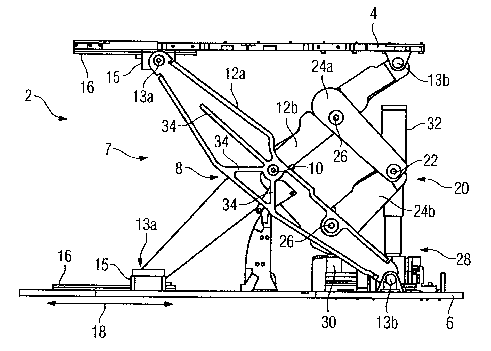
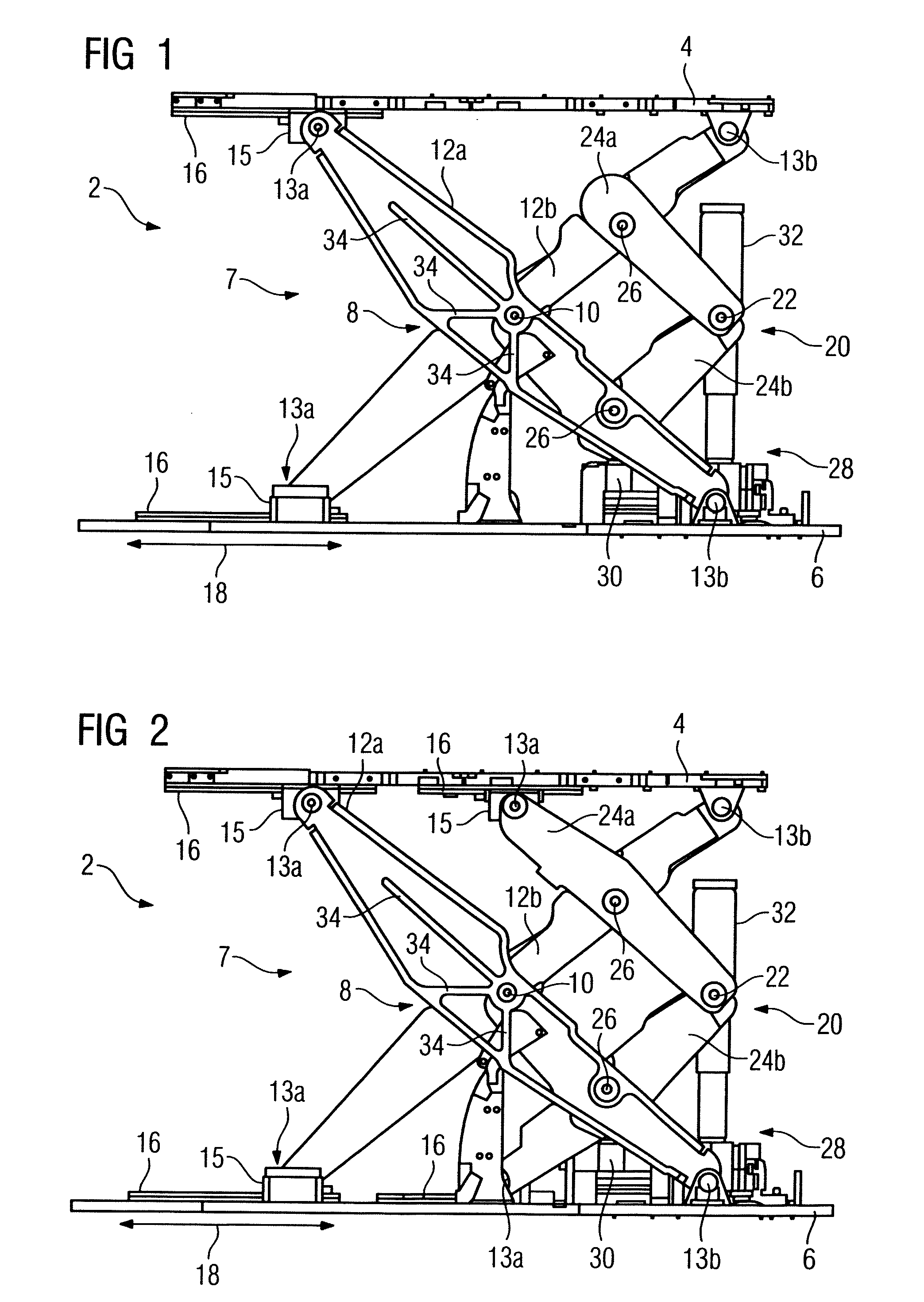
[0025]FIG. 1 shows a lifting device 2 for adjusting the height of a top part 4 relative to a base part 6. The top part 4 and the base part 6 are both in the form of a panel in this exemplary embodiment. In particular, the lifting device 2 is provided for adjusting the height of a patient couch (not shown) which is mounted on the top part 4. The movement of the top part 4 is performed via an elevator mechanism 7. The elevator mechanism 7 includes a scissor mechanism 8, which has two scissor arms 12a, 12b that cross each other at a scissor pivot joint 10. Each of the scissor arms 12a, 12b is mounted on the top panel 4 and base panel 6 via a movable mounting connection 13a and a fixed mounting connection 13b.

[0026]For the movable mounting, the scissor arms 12a, 12b are linked to slides 15. When the scissor mechanism 8 is opened and closed, the slides 15 slide back and forth in direction of travel 18 on a rail 16 which is attached to the corresponding panel 4, 6, thereby guiding the sc...


PUM


Abstract

A lifting device adjusts the height of a top part relative to a base part for a patient couch. The lifting device includes an elevator mechanism and a drive unit for height adjustment. The elevator mechanism has a scissor mechanism with two scissor arms, which are pivotably connected together via a scissor pivot joint. The elevator mechanism further includes an elbow mechanism having two elbow arms, which are pivotably connected together via an elbow pivot joint. Each of the elbow arms is linked to a scissor arm via a linking pivot joint.

Description

[0001]The present patent document claims the benefit of German patent application DE 10 2007 007 101.0, filed Feb. 13, 2007, which is hereby incorporated by reference.BACKGROUND[0002]The present embodiments relate to a lifting device for adjusting the height of a top part relative to a base part for a patient couch (e.g., support, table, or stretcher).[0003]Lifting devices of this kind are known from the prior art and are used for the vertical positioning of a patient couch or a patient table. The top part and the base part are usually embodied in the form of panels or frames which can be moved relative to each other by an elevator mechanism, thereby resulting in a height adjustment of the top part relative to the base part.[0004]A suitable elevator mechanism for a lifting device is, for example, a simple scissor mechanism. A simple scissor mechanism is a paired embodiment of two levers which cross each other at a scissor pivot joint. The two “scissors” are configured in parallel wi...

Claims


Application Information

Patent Timeline
IPC IPC(8): B66B9/02B66F3/22
CPCB66B9/02A61G7/012
Inventor HOTH, TOBIAS
Owner SIEMENS HEALTHCARE GMBH
Why Eureka
Try Eureka