Screen for a Vibratory Separator Having Tension Reduction Feature

a technology of vibratory separator and screen, which is applied in the direction of screening, solid separation, chemistry apparatus and processes, etc., can solve the problem of preventing the flow of material through the opening

Inactive Publication Date: 2008-08-14
LUMSDEN CORP
View PDF7 Cites 28 Cited by
  • Summary
  • Abstract
  • Description
  • Claims
  • Application Information

AI Technical Summary

Problems solved by technology

In the above described screen, problems occur in that the openings in the woven wire cloth can become blocked, which impedes the flow of the material through the openings.
This phenomenon is typically referred to as “blinding.” Additionally, if the material has a substantially triangular or arrowhead shape, the material may become lodged in the openings thereby blocking the openings in the woven wire cloth.

Method used


Image

  • Screen for a Vibratory Separator Having Tension Reduction Feature
  • Screen for a Vibratory Separator Having Tension Reduction Feature
  • Screen for a Vibratory Separator Having Tension Reduction Feature

Examples


first embodiment

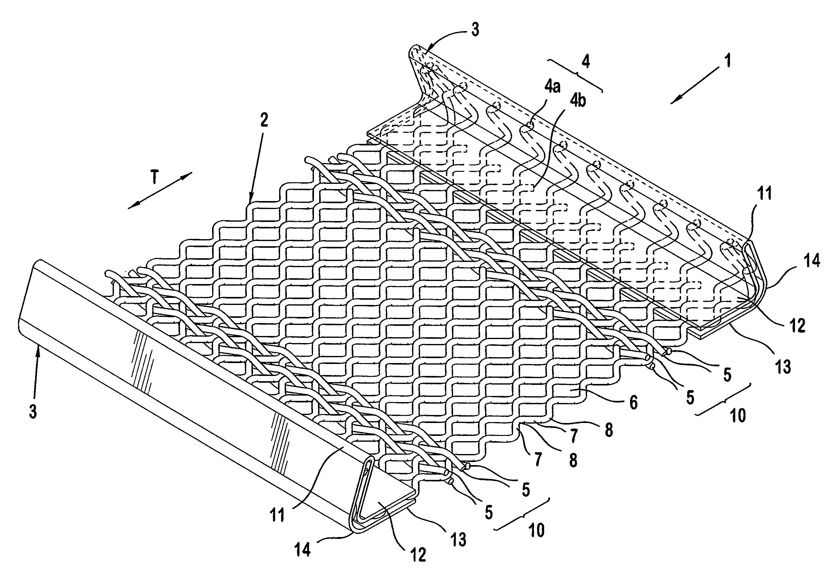
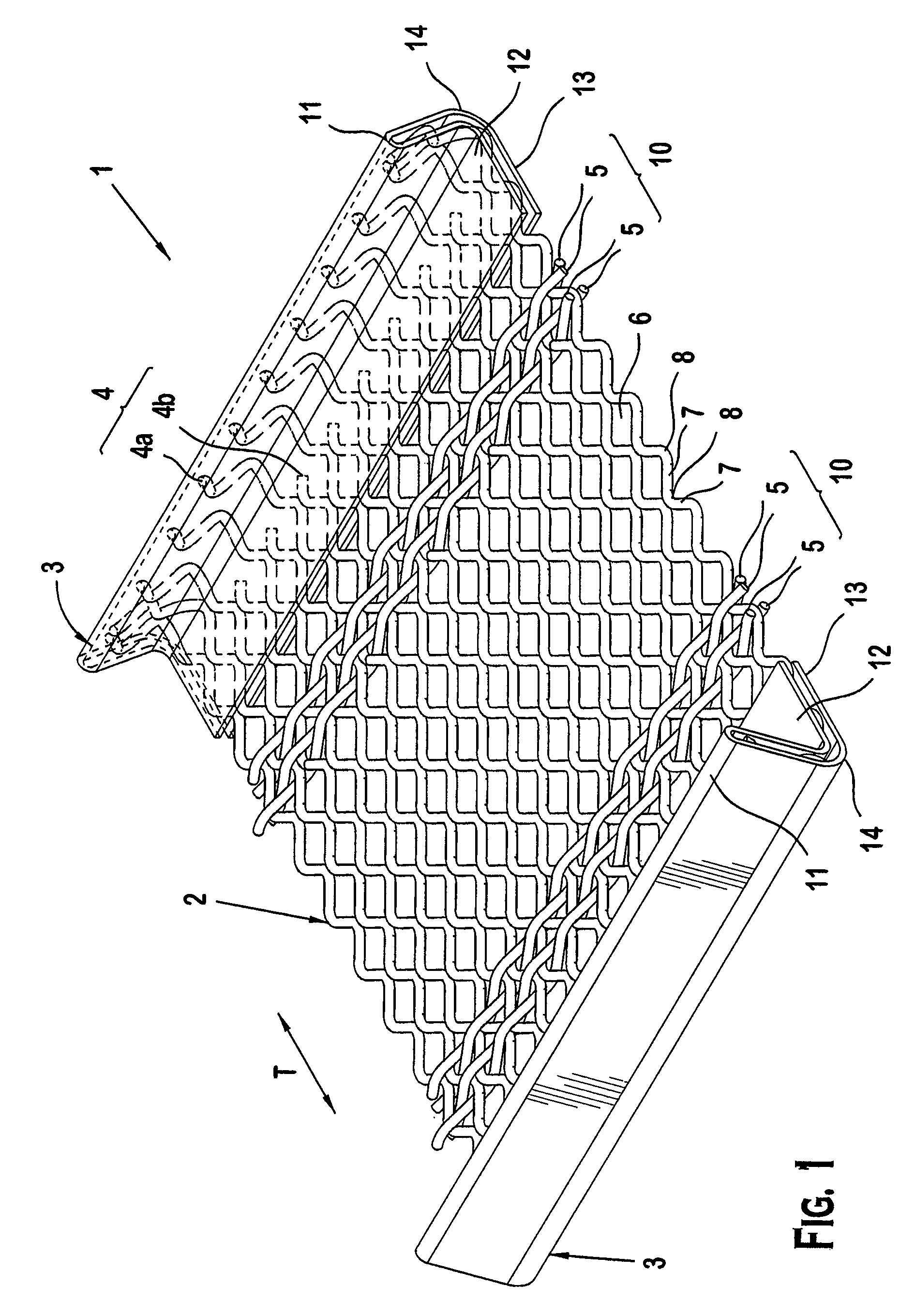
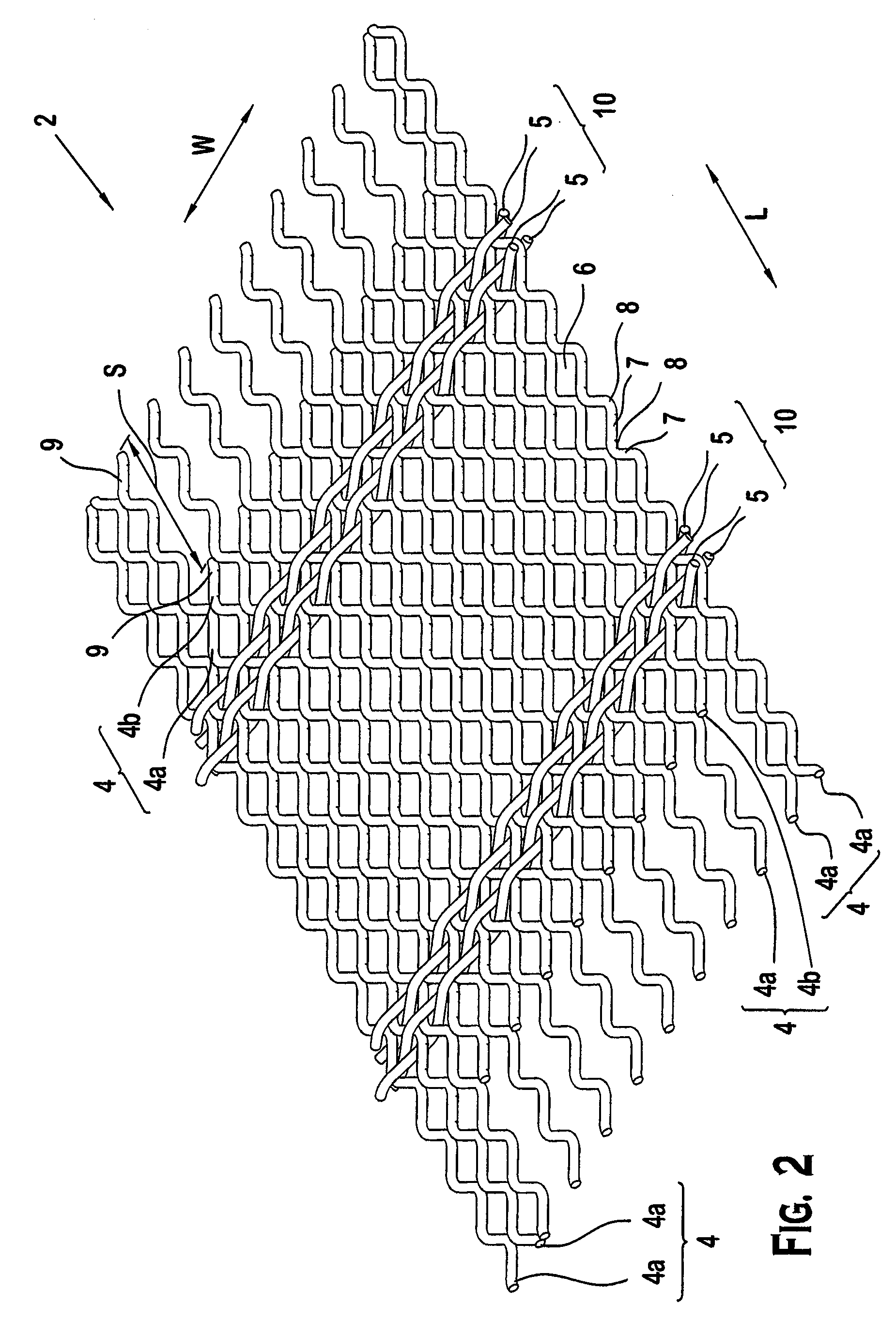
[0014]FIGS. 1-2 show a screen 1 for a vibratory separator according to the invention. As shown in FIG. 1, the screen 1 comprises a woven wire cloth 2 that extends between a pair of holding members 3. As shown in FIG. 2, the woven wire cloth 2 includes a plurality of warp wires 4 and a plurality of fill or weft wires 5. The warp wires 4 are disposed substantially in a common plane and are arranged substantially parallel to each other. Each of the warp wires 4 has a substantially wave shape formed by a succession of substantially straight portions 7 connected together by oppositely bent portions 8. Each of the warp wires 4 has substantially the same diameter. Although the warp wires 4 are shown as round wires in the illustrated embodiment, the warp wires 4 may also be shaped wires.

[0015]As shown in FIG. 2, the warp wires 4 are arranged in pairs. The pairs of warp wires 4 arranged at a perimeter of the woven wire cloth 2 consist of first warp wires 4a. The remaining pairs of warp wires...

second embodiment

[0025]FIGS. 6-8 show a screen 201 for a vibratory separator according to the invention. As shown in FIG. 6, the screen 201 comprises a woven wire cloth 202 that extends between a pair of holding members 203. As shown in FIG. 7, the woven wire cloth 202 includes a plurality of warp wires 204 and a plurality of fill or weft wires 205. The warp wires 204 are disposed substantially in a common plane and are arranged substantially parallel to each other. The warp wires 204 are substantially the same length with respect to a direction of length L of the woven wire cloth 202. Each of the warp wires 204 has a substantially wave shape formed by a succession of substantially straight portions 207 connected together by oppositely bent portions 208. Although the warp wires 204 are shown as shaped wires in the illustrated embodiment, the warp wires 204 may also be round wires.

[0026]As shown in FIG. 7, the warp wires 204 are arranged in pairs. The pairs of warp wires 204 arranged at a perimeter o...


PUM


Abstract

A screen for a vibratory separator includes holding members and a woven wire cloth. The woven wire cloth has a plurality of warp wires extending between the holding members. The warp wires define openings in the woven wire cloth for the passage of material there through. The warp wires are arranged in pairs consisting of a first warp wire and a second warp wire. The warp wires are fixed to the holding members such that the first warp wire in each of the pairs has a greater tension applied thereto than the second warp wire in each of the pairs.

Description

FIELD OF THE INVENTION[0001]The invention relates to a screen for a vibratory separator comprising a woven wire cloth having a plurality of warp wires extending between holding members wherein the warp wires are arranged in pairs and the warp wires are fixed to the holding member such that one of the warp wires in each of the pairs has a greater tension applied thereto than the other warp wire in each of the pairs.BACKGROUND[0002]Screens mounted on vibratory separators are typically used by quarries to separate loose or suspended materials by grade and / or size. The screen typically consists of a woven wire cloth having a plurality of wires arranged and configured to form a plurality of openings therein. As the screen is vibrated, the material having a smaller size than the openings in the woven wire cloth is passed through the openings in the woven wire cloth, and the material having a larger size than the openings in the woven wire cloth are vibrated over and off of a top surface o...

Claims


Application Information

Patent Timeline
Patent Type & Authority Applications(United States)
IPC IPC(8): B07B1/46
CPCB07B1/4672B07B1/50B07B1/48
Inventor YOUNG, CHARLES A.
Owner LUMSDEN CORP
Why Eureka
Try Eureka