Machine having electrical power system and method

a technology of electrical power generation and machine, applied in mechanical power/torque control, electric energy management, gas pressure propulsion mounting, etc., can solve the problems of increasing the internal inertia of the generator, causing mounting and other hardware-related problems, and significant torque spikes in the system

Active Publication Date: 2008-08-14
CATERPILLAR INC
View PDF13 Cites 10 Cited by
  • Summary
  • Abstract
  • Description
  • Claims
  • Application Information

AI Technical Summary

Benefits of technology

[0009]In still another aspect, the present disclosure provides a method of operating a machine system that includes the step of rotating a generator of the machine system with an engine of the machine system, the generator having a speed range that includes a resonance speed associated with resonance vibrations of the machine system. The method further includes t

Problems solved by technology

While the aforementioned developments have provided improvements to certain machines, particularly in environments where jurisdictional regulations set forth relatively high standards for emissions and efficiency, a variety of new challenges have arisen.
Hence, electrical power systems for such machines often employ a generator with a relatively large rotor and other components, necessarily increasing the generator's internal inertia.
The high generator inertia can give rise to mounting and other hardware-related challenges due to vibrations and inertia reflection between the engine and generator.
This can be particularly problematic where the generator i

Method used


Image

  • Machine having electrical power system and method
  • Machine having electrical power system and method
  • Machine having electrical power system and method

Examples


Embodiment Construction

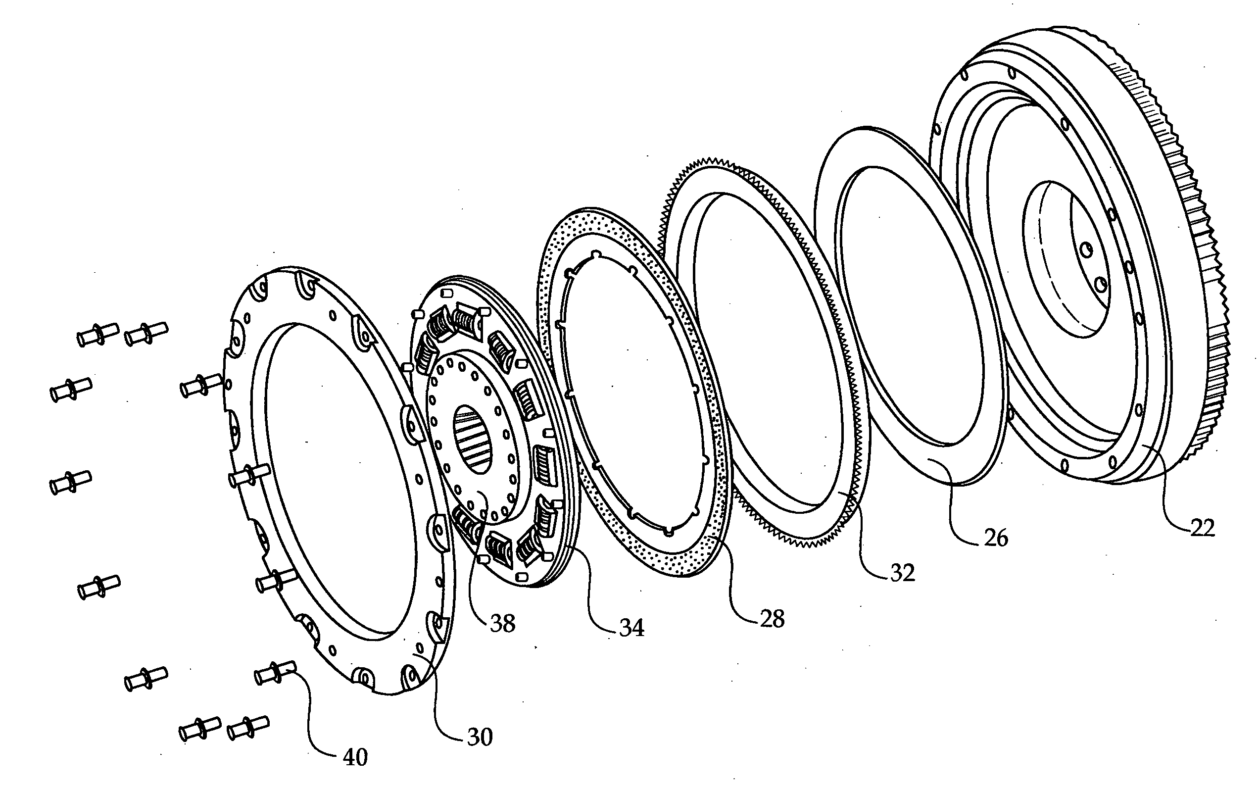
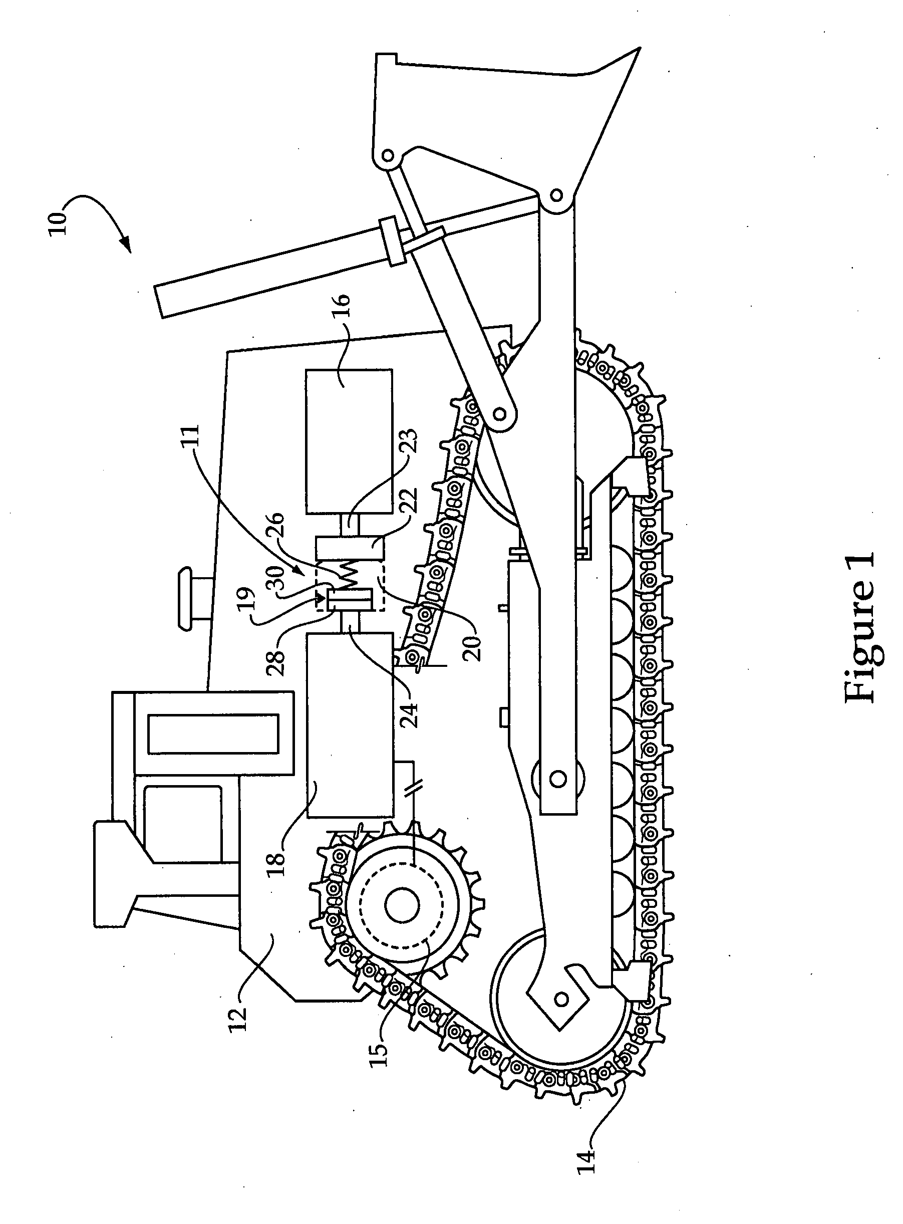
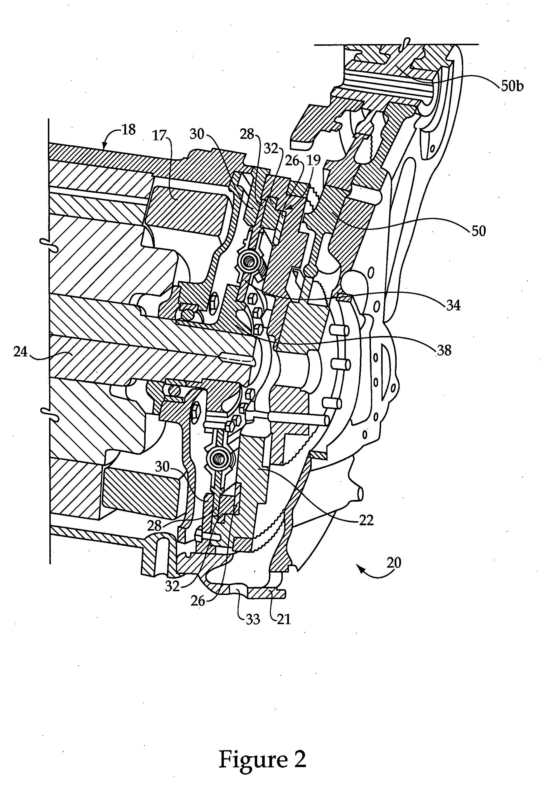
[0015]Referring to FIG. 1, there is shown a machine 10 according to one embodiment. Machine 10 will typically include a mobile electric drive machine having a frame 12 with an electrical power system 11 mounted thereon. Electrical power system 11 may include an engine 16 configured to rotate a generator 18 which is configured to provide electrical power for machine 10. Machine 10 may further include a set of ground engaging elements such as tracks 14, only one of which is visible in FIG. 1, for propelling machine 10. Machine 10 will also typically include a drive coupling 20 configured for transmitting torque between engine 16 and generator 18 having a configuration and operation providing advantages over earlier strategies, particularly with regard to machine component strain and operating smoothness, as further described herein.

[0016]At least one electric motor 15 may be further provided which is coupled with generator 18 and configured to drive tracks 14. Motor 15, together with ...


PUM


Abstract

A machine and electrical power system includes a generator having a speed range that includes a resonance speed associated with resonance vibrations of the system. A drive coupling is disposed between the generator and an engine configured to rotate the generator and is further configured to transmit torque from the engine to the generator, the drive coupling being configured to allow relative slip between first and second elements when the generator is rotated at its resonance speed. A machine operation method includes rotating a generator with an engine, and generating resonance vibrations of at least one of the engine and the generator by rotating the generator at a resonance speed. The method further includes inhibiting transmitting resonance vibrations between the generator and the engine by allowing relative rotational slip within a drive coupling disposed between the engine and the generator.

Description

TECHNICAL FIELD[0001]The present disclosure relates generally to machines having electrical power generation systems and associated operating strategies, and relates more particularly to an electrical power system and method wherein a drive coupling within the system is configured to inhibit transmission of resonance vibrations between an engine and generator.BACKGROUND[0002]The combination of a combustion engine such as an internal combustion engine and a generator to produce electrical power has been known for many years. Relatively more recently, however, engine-driven generators have been used in electrically powered mobile machines to provide electrical power for propulsion and operation of other machine systems. In such strategies, rather than requiring relatively rapid ramp-up and down of engine output to accommodate changes in power demand, relatively more stable, smooth operation and transition across an engine power output range may be achieved. In other words, by powering...

Claims


Application Information

Patent Timeline
IPC IPC(8): F02D35/00B60K6/20G05D17/02
CPCB60K6/387Y02T10/642B60W10/02B60W20/00B60W30/20B60W2300/44B60W2710/025B60Y2200/411F02D29/06F16D3/66F16D7/025F16F15/123Y02T10/6217B60L11/123B60L15/20B60L2200/40B60L2240/12B60L2240/421B60L2240/423B60L2240/441B60L2240/443B60L2240/507B60L2270/145Y02T10/7077Y02T10/7275B60K6/46B60L50/61Y02T10/62Y02T10/64Y02T10/70Y02T10/72B60W2510/0241Y02T10/7072
Inventor SAVANT, SATISHKOUGH, BRADFORD A.FEE, DAVID M.BAUMANN, JONATHANDAMES, MATTHEW
Owner CATERPILLAR INC
Why Eureka
Try Eureka