Method and system for reducing effects of undesired signals in an infrared imaging system

a technology of infrared imaging and undesired signals, applied in the field of active infrared (ir) imaging, can solve the problems of more difficult programming of computer systems to automatically set limits to differentiate between desirable signals and types of signals, and achieve the effect of reducing the effects of undesired ir sources

Inactive Publication Date: 2008-08-14
MICROSOFT TECH LICENSING LLC
View PDF70 Cites 45 Cited by
  • Summary
  • Abstract
  • Description
  • Claims
  • Application Information

AI Technical Summary

Benefits of technology

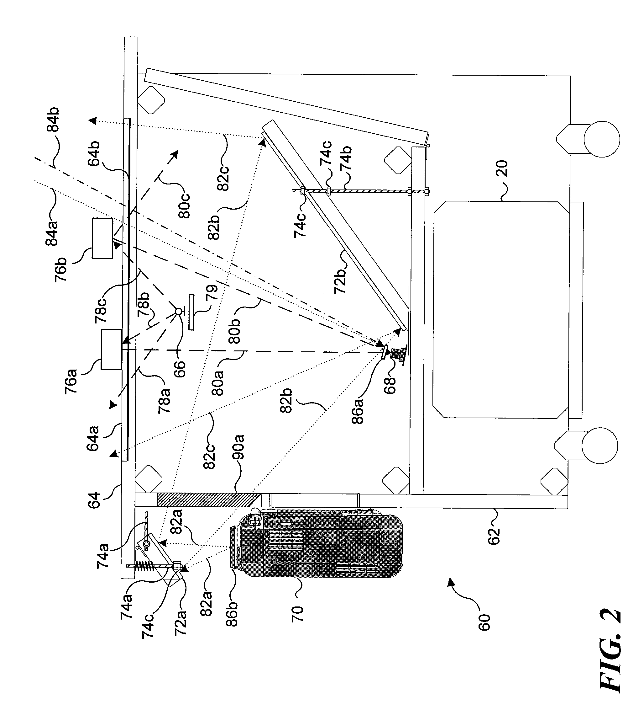
[0011]One of the more important functions of the present invention is to reduce the effects of undesired IR sources, including ambient sources such as sunlight, incandescent light, and other IR sources, in an IR imaging system. Imaging data are captured both when the IR source controlled by the IR imaging system is activated and when it is not. The imaging data collected when the controlled IR source is deactivated are imaging data based on undesired IR sources. Thus, by pixelwise subtracting a set of imaging data collected when the IR source was deactivated, from a set of imaging data collected when the IR source was activated, the resulting composite set of imaging data should include only imaging data resulting from illumination generated by the controlled IR source.
[0012]One aspect of the present invention is thus directed to a method for reducing effects of undesired IR light sources in an imaging system using an IR light source. The IR light source is activated during a first image capture interval, and a first set of imaging data is captured during the first image capture interval. The IR light source is then deactivated, and a second set of image data is captured during the second image capture interval. A composite set of image data is then generated by subtracting from first values in the first set of image data corresponding second values in the second set of image data.

Problems solved by technology

Automated signal processing systems, where a computer system autonomously responds to input signals, present a more difficult problem.
Unlike the example of a squelch control noted above, where a user can adjust the squelch level based on experience and judgment, it is more difficult to program a computer system to automatically set a limit to differentiate between types of signals that are desirable and those that are not.
Anyone who has used speech recognition programs has experienced some difficulty when the computer fails to recognize something the user said, which happens more often if there is any background noise or other sounds that affect the auditory input perceived by the computer.
Computer vision arguably is a much more intricate problem than speech recognition.
If the computer must process too many visual signals or too broad a range of visual signals, the input will more likely be misread by the computer.
On the other hand, if the computer suppresses too many visual signals, the computer also may misread visual inputs or ignore intended visual inputs entirely.
If the systems responded to visible light, visible light projected by the systems and reflected back by the interactive surface could lead to false readings by the computing system.
Further, even if reflections could be suppressed, unless the system is disposed in a dark room, room lights and other visible light passing through the interactive display surface would substantially adversely affect the computer vision systems.
However, although people are generally aware of the IR content of light produced by most sources, because it is not visible to the naked eye, ambient IR light signals that might adversely impact computer vision systems also are very common.
These unintended IR signals, just like unintended visible light signals, can provide undesired input to IR-sensitive computer vision systems.
Band-pass type filters can suppress visible light and other non-IR light, but they are not helpful in separating IR light reflected from an object that is to be detected from background IR light.

Method used


Image

  • Method and system for reducing effects of undesired signals in an infrared imaging system
  • Method and system for reducing effects of undesired signals in an infrared imaging system
  • Method and system for reducing effects of undesired signals in an infrared imaging system

Examples


Embodiment Construction

Exemplary Computing System for Implementing Present Invention

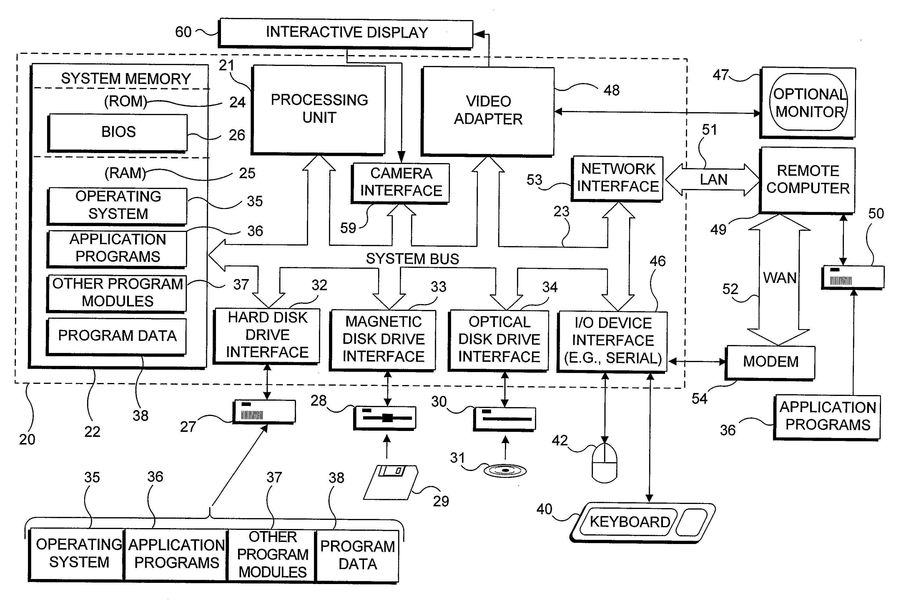
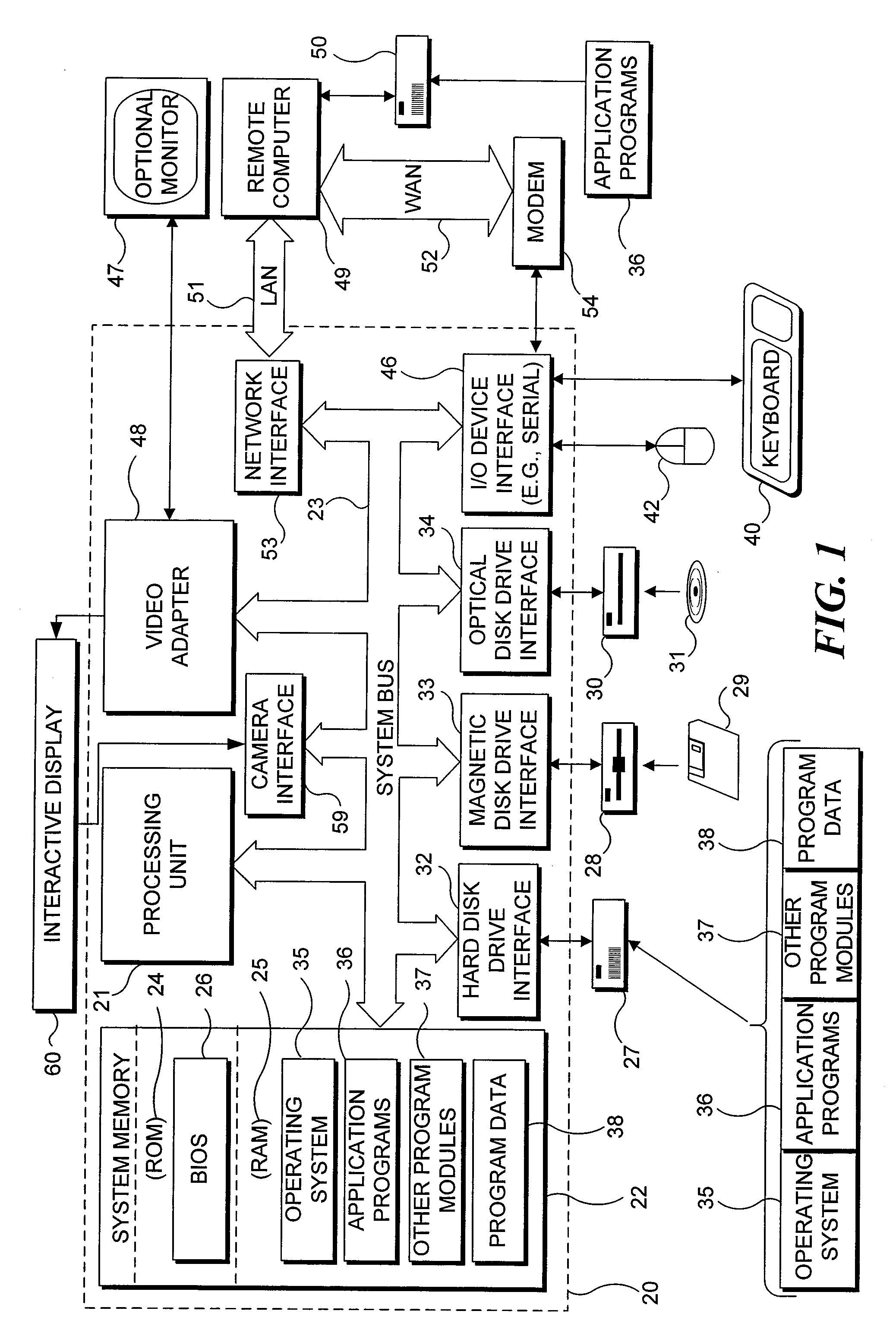
[0029]With reference to FIG. 1, an exemplary system suitable for implementing various portions of the present invention is shown. The system includes a general purpose computing device in the form of a conventional PC 20, provided with a processing unit 21, a system memory 22, and a system bus 23: The system bus couples various system components including the system memory to processing unit 21 and may be any of several types of bus structures, including a memory bus or memory controller, a peripheral bus, and a local bus using any of a variety of bus architectures. The system memory includes read only memory (ROM) 24 and random access memory (RAM) 25. A basic input / output system 26 (BIOS), containing the basic routines that help to transfer information between elements within the PC 20, such as during start up, is stored in ROM 24. PC 20 further includes a hard disk drive 27 for reading from and writing to a hard disk (no...


PUM


Abstract

Effects of undesired infrared light are reduced in an imaging system using an infrared light source. The desired infrared light source is activated and a first set of imaging data is captured during a first image capture interval. The desired infrared light source is then deactivated, and a second set of image data is captured during a second image capture interval. A composite set of image data is then generated by subtracting from first values in the first set of image data corresponding second values in the second set of image data. The composite set of image data thus includes a set of imaging where data all infrared signals are collected, including both signals resulting from the IR source and other IR signals, from which is subtracted imaging in which no signals result from the IR course, leaving image data including signals resulting only from the IR source.

Description

CROSS-REFERENCE TO RELATED APPLICATIONS[0001]This application claims priority to, the benefit of, and is a divisional application of co-pending U.S. patent application Ser. No. 10 / 870,777, filed Jun. 16, 2004, entitled “Methods and System for Reducing Effects of Undesired Signals in an Infrared Imaging System,” which issued as U.S. Pat. No. ______, on ______, and hereby expressly incorporates the entire contents of such application.FIELD OF THE INVENTION[0002]The present invention generally pertains to active infrared (IR) imaging, and more specifically, to removing IR signals received from unintended and undesired IR sources in a region of interest to improve the quality of imaging data resulting from the active IR source.BACKGROUND OF THE INVENTION[0003]The presence of undesired signals is a concern in the processing of virtually all electromagnetic signals. Even in a relatively simple system, such as a radio, a squelch control is often provided to attenuate signals below a certai...

Claims


Application Information

Patent Timeline
Patent Type & Authority Applications(United States)
IPC IPC(8): G06K9/40G06F3/042G06K9/00H04N5/225H04N5/33
CPCG06F3/0421H04N5/33H04N5/2256G06K9/00375G06V40/107H04N23/56
Inventor WILSON, ANDREW D.
Owner MICROSOFT TECH LICENSING LLC
Why Eureka
Try Eureka