Tapered Cable For Use In Fiber To The Premises Applications

a technology of fiber to the premises and tapered cables, applied in the direction of optics, fibre mechanical structures, instruments, etc., can solve the problems of reducing the requiring special equipment and specially trained technicians, and requiring careful handling of optical fibers. , to achieve the effect of reducing the minimum working radius of the cabl

Active Publication Date: 2008-08-14
AFL COMM LLC
View PDF7 Cites 143 Cited by
  • Summary
  • Abstract
  • Description
  • Claims
  • Application Information

AI Technical Summary

Benefits of technology

[0012]Accordingly, an aspect of the present invention is to provide a tapered cable involving the use of small stand alone cables that can be bundled together. Where breakouts are required, one of the bundled cables is routed away from the bundled cable. Each breakout cable contains a predetermined number of optical fibers each outfitted with fiber connectors. Further, each cable and each optical fiber can be set at a predetermined length so as to reach a terminal device without the need for additional splicing or intervening connectors. Also, the inclusion of external protective members may be eliminated such that the minimum working radius of the cable may be reduced.

Problems solved by technology

However, providing these numerous individual access points has many drawbacks.
The drawback of this method is it requires special equipment and specially trained technicians to perform the task which can be quite costly.
These conventional techniques create an invasive risk as well as associated costs.
Optical fibers are extremely fragile and must be handled carefully to avoid breakage.
Knots, kinks, twists and bends in the optical fiber will ruin the fiber's ability to transmit light.
In some cases, a bend or break in an optical fiber will completely disrupt a system's performance.
Additionally, there is a high cost associated with optical fiber splicing.
As the number of splices done in a fiber to the premises type application is rather small, the cost per splice may be high given the labor cost and the time required to splice the fiber.
A disadvantage of this system is that excess hardware and connectors are required to bring the optical network to a terminal device.
Another drawback of this approach is increased installation cost.
Thus, installation becomes more difficult as working product exhibits reduced flexibility.
Additionally, where specific installations induce bends in the cable when installed, the rate of fiber damage during installation may increase.

Method used


Image

  • Tapered Cable For Use In Fiber To The Premises Applications
  • Tapered Cable For Use In Fiber To The Premises Applications
  • Tapered Cable For Use In Fiber To The Premises Applications

Examples


Embodiment Construction

[0026]Reference is now made to the drawings, in which the same reference numerals are used throughout the different drawings to designate the same or similar components.

[0027]With reference to the accompanying drawings, exemplary embodiments of the present invention are described in detail below.

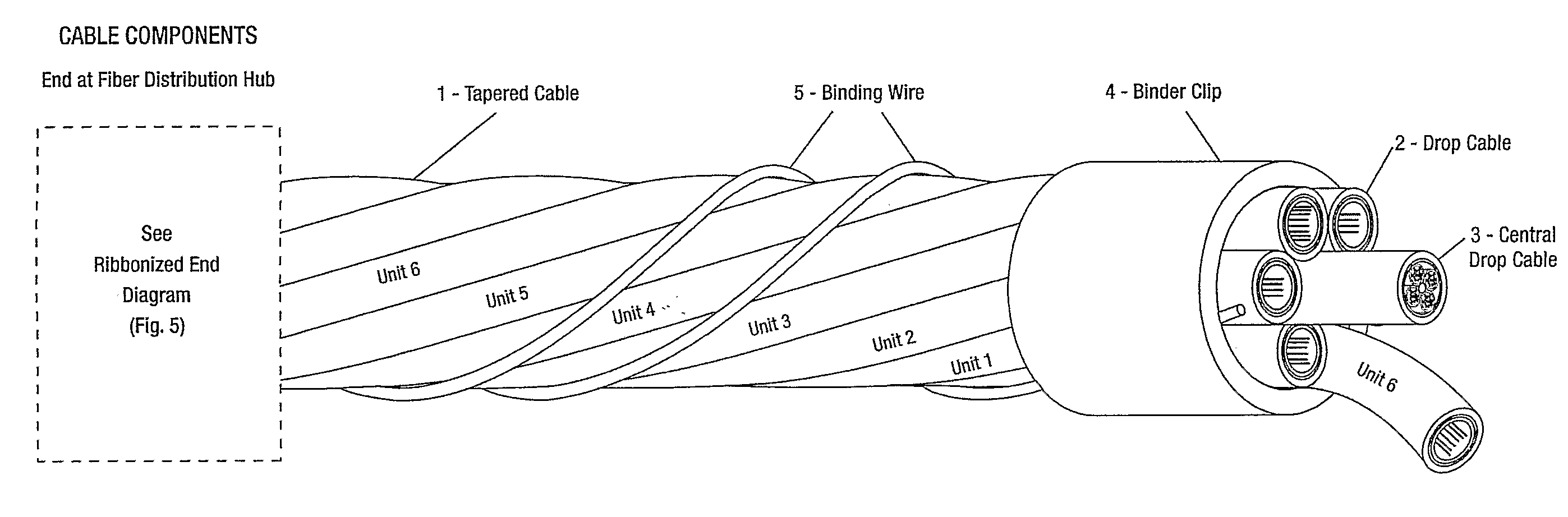
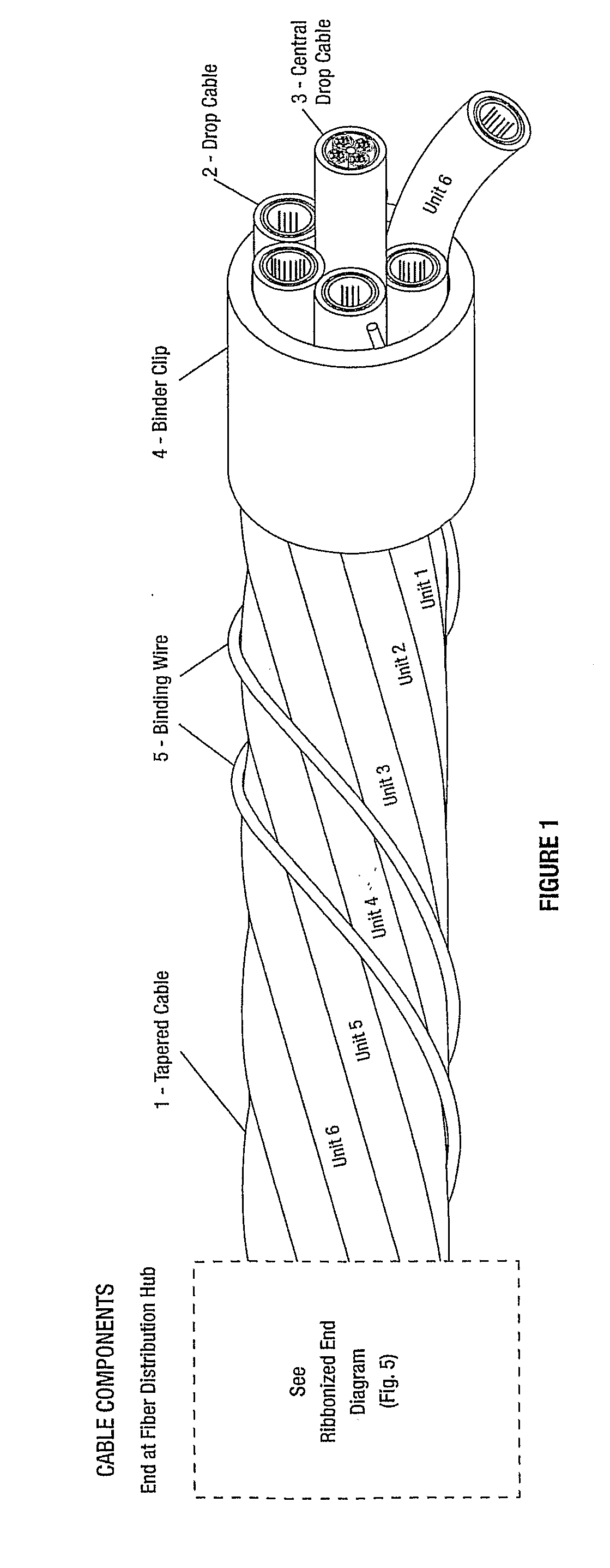
[0028]FIG. 1 is a view of a tapered cable 1 according to one exemplary embodiment of the present invention. In this exemplary embodiment, six drop cables 2 are helically wound around central drop cable 3. The drop cables 2 and the central drop cable 3 are bound together using binder clip 4 and binding wire 5. However, the present invention is not so limited and, thus, the number of drop cables 2 and the method of binding the drop cables 2 together may vary. For example, the central drop cable 3 may be omitted and the number of drop cables 2 desired for a particular application may be bound together without being helically wound. Additionally, the binder clip 4 and the binding wire 5 need not...


PUM


Abstract

A tapered fiber optic distribution cable that includes a plurality of drop cables (2) having at least one predetermined breakout location where a drop cable is withdrawn from the tapered distribution cable. The drop cables are bound together to form the tapered fiber optic distribution cable by binding members (5) or helical winding. Each drop cable (2) contains a plurality of optical fibers which may be reconnectorized according to a user's preferences.

Description

CROSS-REFERENCE TO RELATED APPLICATION[0001]This application claims priority from provisional application 60 / 707,553 filed on Aug. 12, 2005, the disclosure of which is incorporated herein by reference in its entirety.BACKGROUND OF THE INVENTION[0002]1. Field of the Invention[0003]The present invention relates to a fiber optic distribution cable and, more specifically, to a factory installed termination system where a standard fiber optic cable is outfitted with fiber optic connections along its length at predetermined locations.[0004]2. Description of the Related Art[0005]The use of optical fibers is becoming increasingly popular. This is by virtue of the growth of a variety of applications; including voice communications, audio / video transmissions, data transmissions, and various other internet related services. Typical applications of optical fiber systems include: cable television services, university campus networks, office networks, industrial plant process control systems, and...

Claims


Application Information

Patent Timeline
Patent Type & Authority Applications(United States)
IPC IPC(8): G02B6/44
CPCG02B6/4471
Inventor HERBST, BRIAN
Owner AFL COMM LLC
Why Eureka
Try Eureka