Utility grid, controller, and method for controlling the power generation in a utility grid

a technology of utility grid and power generation, applied in the direction of mechanical power/torque control, dc source parallel operation, wind energy generation, etc., can solve the problems of not only an amount, but also the power output of the generator of a wind farm may change,

Active Publication Date: 2008-08-14
GENERAL ELECTRIC CO
View PDF7 Cites 136 Cited by
  • Summary
  • Abstract
  • Description
  • Claims
  • Application Information

AI Technical Summary

Benefits of technology

[0008]According to a further aspect a controller for controlling the output power of an intermittent renewable energy source is provided. The controller includes at least one forecasting means providing at least one forecasting variable, wherein the controller is adapted to control the...

Problems solved by technology

However, because wind speed and air density change over time, power output from the generators of a wind farm may also change over time, sometimes even falling to zero when wind speed drops below a minimum threshold.
Variations in power output from such wind farms may cause variations not only in an amount of power flow...

Method used


Image

  • Utility grid, controller, and method for controlling the power generation in a utility grid
  • Utility grid, controller, and method for controlling the power generation in a utility grid
  • Utility grid, controller, and method for controlling the power generation in a utility grid

Examples


Embodiment Construction

[0021]Reference will now be made in detail to the various embodiments of the invention, one or more examples of which are illustrated in the figures. Each example is provided by way of explanation of the invention, and is not meant as a limitation of the invention. For example, features illustrated or described as part of one embodiment can be used on or in conjunction with other embodiments to yield yet a further embodiment. It is intended that the present invention includes such modifications and variations.

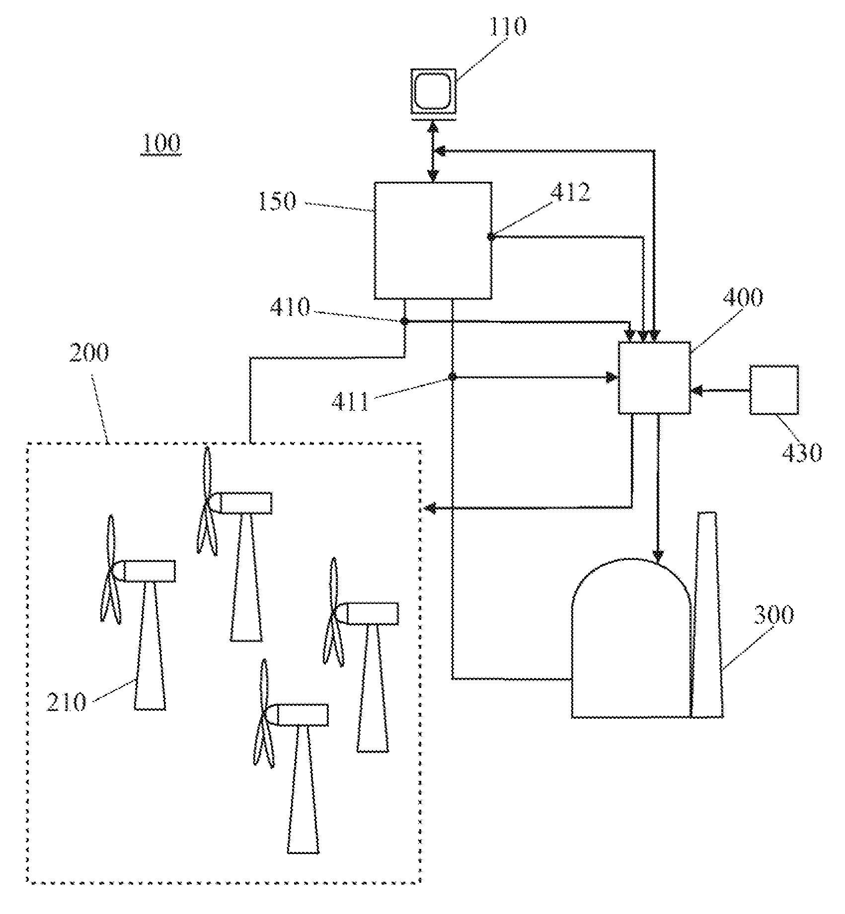
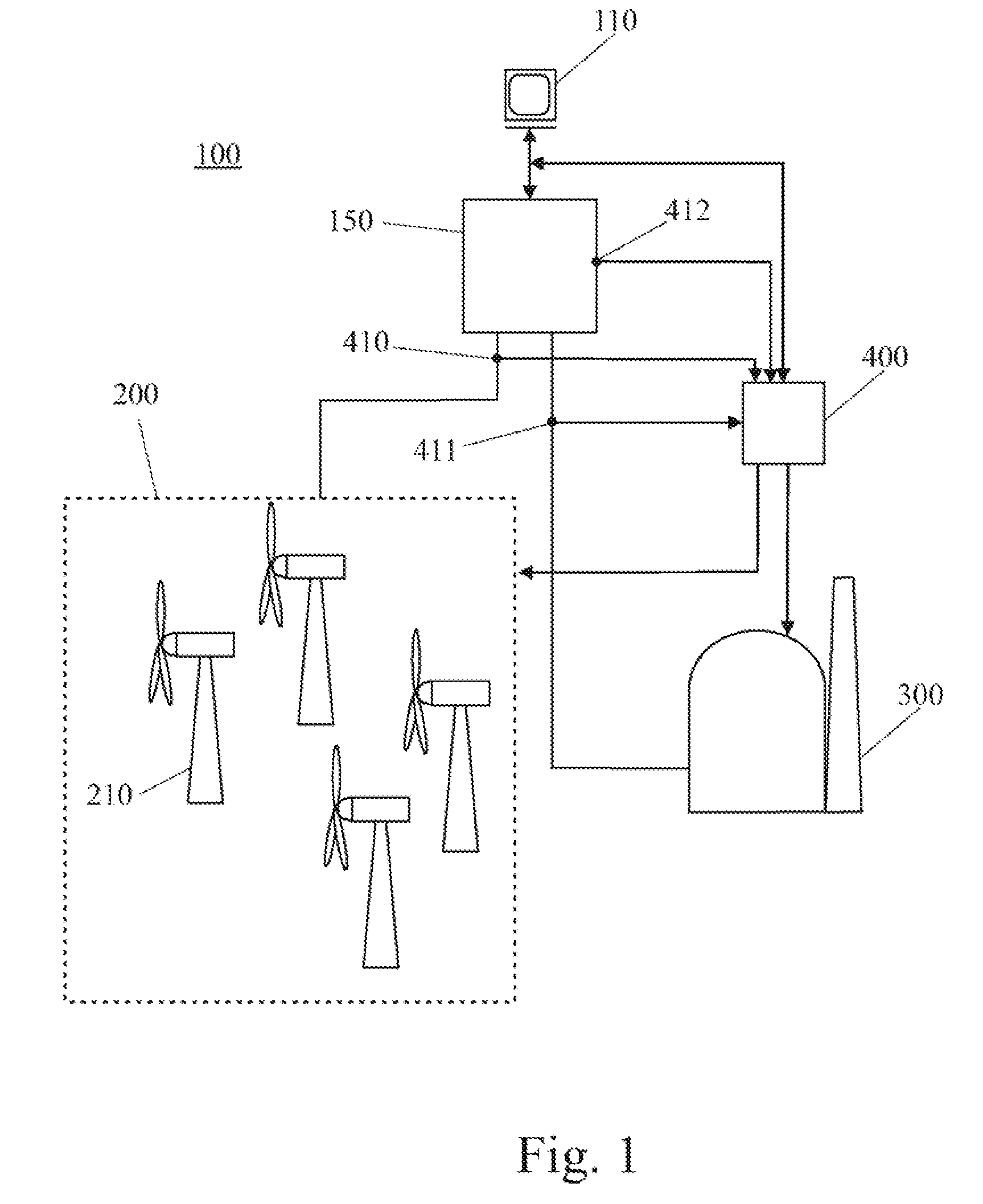
[0022]FIG. 1 shows a schematic representation of a utility grid according to an embodiment of the present invention. Therein, the utility grid 100 includes a centralized grid control 110 which monitors and controls power production and power consumption within the grid, grid frequency or the like. In FIG. 1, only part of the grid is shown in detail while most of the network structure is schematically represented by reference numeral 150. It will be understood by those skilled i...


PUM


Abstract

A utility grid is provided, the utility grid comprising a centralized control means, an intermittent renewable energy source for generating electrical power: at least one further power generation system; and at least one local controller for controlling the total power output of said intermittent renewable energy source and said as least one further power generation system, wherein the centralized control means is connected with the at least one local controller and adapted to request a desired total power output from the local controller.

Description

BACKGROUND OF THE INVENTION[0001]The present invention relates to a utility grid, a controller, and a method for controlling the power generation in a utility grid.[0002]Wind energy is often used to generate electrical power at power plants, often referred to as wind farms, using, for example, the rotation of large wind turbines to drive electrical generators. However, because wind speed and air density change over time, power output from the generators of a wind farm may also change over time, sometimes even falling to zero when wind speed drops below a minimum threshold. Variations in power output from such wind farms may cause variations not only in an amount of power flowing from the farm but also in the frequency of a power system to which the electrical power is delivered for consumption thereof. A group of power systems, power plants, and associated infrastructure spread over a geographical area is sometimes referred to as a grid. A drop in power output from the wind farm can...

Claims


Application Information

Patent Timeline
IPC IPC(8): G06G7/10H02J3/38H02P9/04
CPCF03D7/0284F03D9/003F05B2250/36F05B2270/337G06Q30/0283Y02E10/725H02J3/382Y02E10/723Y04S50/14H02J3/383H02J3/386Y02E10/563Y02E10/763H02J3/46Y02P80/14F03D9/255F03D9/257H02J2300/10H02J2300/28H02J2300/20H02J2300/24H02J3/381Y02E10/56Y02E10/72Y02E10/76H02J3/466
Inventor LUTZE, HANS HENNINGBUCKER, ANDREAS
Owner GENERAL ELECTRIC CO
Why Eureka
Try Eureka