Cross lapper

Inactive Publication Date: 2008-08-21
DILO MASCHF OSKAR
View PDF3 Cites 8 Cited by
  • Summary
  • Abstract
  • Description
  • Claims
  • Application Information

AI Technical Summary

Benefits of technology

[0009]It is therefore the object of the invention to provide a cross lapper of the above-mentioned kind, which has a

Problems solved by technology

Due to this reason it is also no longer possible to guide the card web transport belt past the la

Method used


Image

  • Cross lapper
  • Cross lapper

Examples


Example

[0019]In the above-mentioned drawings only the parts essential for explaining the invention are shown in order not to load the drawings with superfluous details. Particularly, a machine frame and the rails on which the movable carriages are movably guided in the machine frame are not shown.

DETAILED DESCRIPTION OF A PREFERRED EMBODIMENT

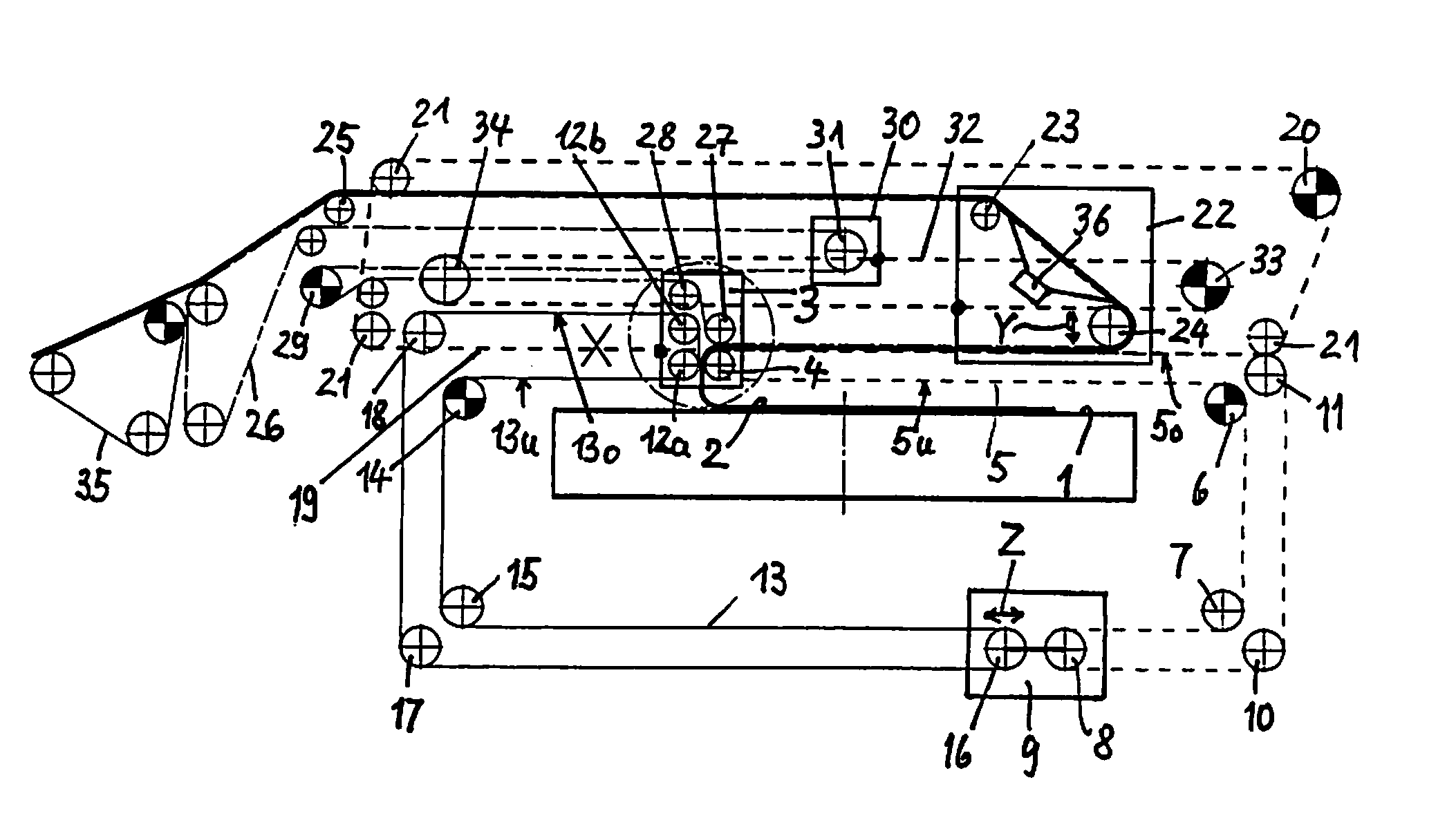
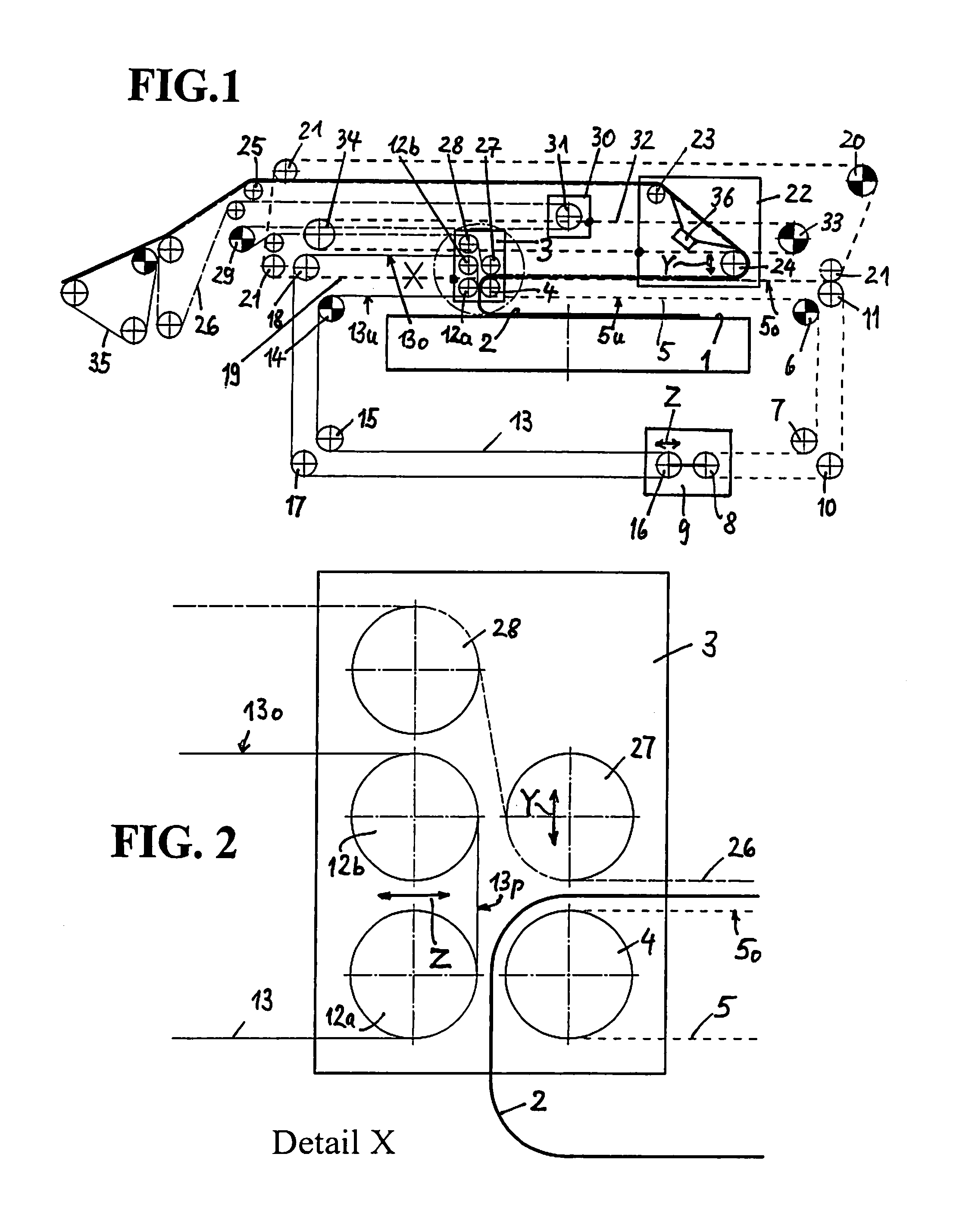
[0020]FIG. 1 shows a schematic view of an embodiment of the invention in a frontal view with respect to the outlet conveyor belt. An endlessly revolving output conveyor belt can be seen in FIG. 1, which is symbolically shown by a rectangle. The output conveyor belt 1 is determined to discharge a laid fleece in a transport direction extending perpendicular with respect to the drawing plane. A starting section of a card web 2 just laid rests on the output conveyor belt 1. A laying carriage 3 can be moved back and forth on rails (not shown) above the output conveyor belt 1. Five deflecting rollers are supported freely rotary in the laying carriage 3 accor...


PUM


Abstract

A cross lapper for laying a fleece from a card web includes a laying carriage movable transversely with respect to an output conveyor belt and an upper carriage as well as a plurality of card web belts to guide the card web over the upper carriage and the laying carriage into a laying nip formed at the laying carriage, wherein a belt inlet is formed at the upper carriage over which a card web transport belt is guided, which from a lower end of an inlet path extends in the direction towards the laying carriage and is accompanied in parallel in this portion by an upper section of a first, endless cover belt guided through the laying carriage, said cover belt enclosing the card web together with same up to the laying carriage. The card web transport belt returned from the laying carriage to the upper carriage leaves the laying carriage above the upper section of a second endless cover belt passed through the laying carriage. This second cover belt forms a baffle surface within the laying carriage above the laying nip and in juxtaposition thereof, said baffle surface ensuring a safe guidance of the card web into the laying nip also case of higher card web transport speeds.

Description

CROSS REFERENCE TO RELATED APPLICATION[0001]This application claims priority to European patent application EP 07 003 212.3, filed Feb. 15, 2007.FIELD OF THE INVENTION[0002]The present invention relates to the field of cross lappers for laying fleece from card webs.BACKGROUND[0003]From U.S. Pat. No. 6,085,391 B1, a cross lapper is known including a laying carriage movable transversely with respect to an output conveyor belt arranged below the output conveyor belt, and an upper carriage as well as a plurality of card web transport belts for transporting the card web over the upper carriage and the laying carriage into a laying nip formed at the laying carriage for depositing the card web on the output conveyor belt.[0004]In the aforementioned cross lapper, a card web input region includes a belt inlet formed of web transport and laying belts (hereinafter card web transport belts), the belt inlet having a downwardly inclined input path with two adjacent belt sections of the card web t...

Claims


Application Information

Patent Timeline
IPC IPC(8): D01G25/00D01G99/00
CPCD01G25/00
Inventor DILO, JOHANN P.LEGER, JOACHIM
Owner DILO MASCHF OSKAR
Why Eureka
Try Eureka