Shoelace reel operated easily and conveniently

a shoelace and reel technology, applied in the field of shoelace reels, can solve the problems of wasting the user's time when tightening or loosening the shoelace, reducing the aesthetic quality of the shoe, and inconvenient use for users, and achieve the effect of convenient user tightening or loosening, convenient operation and convenient operation

Inactive Publication Date: 2008-08-21
MENG HANN PLASTIC
View PDF6 Cites 104 Cited by
  • Summary
  • Abstract
  • Description
  • Claims
  • Application Information

AI Technical Summary

Benefits of technology

[0006]The primary objective of the present invention is to provide a shoelace reel that is operated easily and conveniently.
[0007]Another objective of the present invention is to provide a shoelace reel, wherein the user only needs to rotate the control knob to tighten the shoelace and to pull out the control knob to loosen the shoelace, so that the shoelace is tightened and loosened easily and quickly.
[0008]A further objective of the present invention is to provide a shoelace reel, wherein the user only needs to operate the control knob to tighten or loosen the shoelace, so that the user can tighten or loosen the shoelace by his one hand only, thereby facilitating the user tightening or loosening the shoelace.
[0009]A further objective of the present invention is to provide a shoelace reel, wherein the ratchet wheel of the drive member is limited by the oneway ratchet teeth of the limit sleeve so that the drive member is rotatable in a oneway manner to prevent the drive member from being rotated in the reverse direction and to prevent the shoelace from being loosened.
[0010]A further objective of the present invention is to provide a shoelace reel, wherein the shoelace is wound around and hidden in the winding zone of the spool to prevent the shoelace from being worn out due to friction, thereby enhancing the lifetime of the shoelace.

Problems solved by technology

However, the user has to stretch the shoelace so as to tighten the shoe and to release the shoelace so as to loosen the shoe, thereby causing inconvenience to the user and wasting the user's time when tightening or loosening the shoelace.
In addition, the shoelace protrudes from the shoe, thereby decreasing the aesthetic quality of the shoe.

Method used


Image

  • Shoelace reel operated easily and conveniently
  • Shoelace reel operated easily and conveniently
  • Shoelace reel operated easily and conveniently

Examples


Embodiment Construction

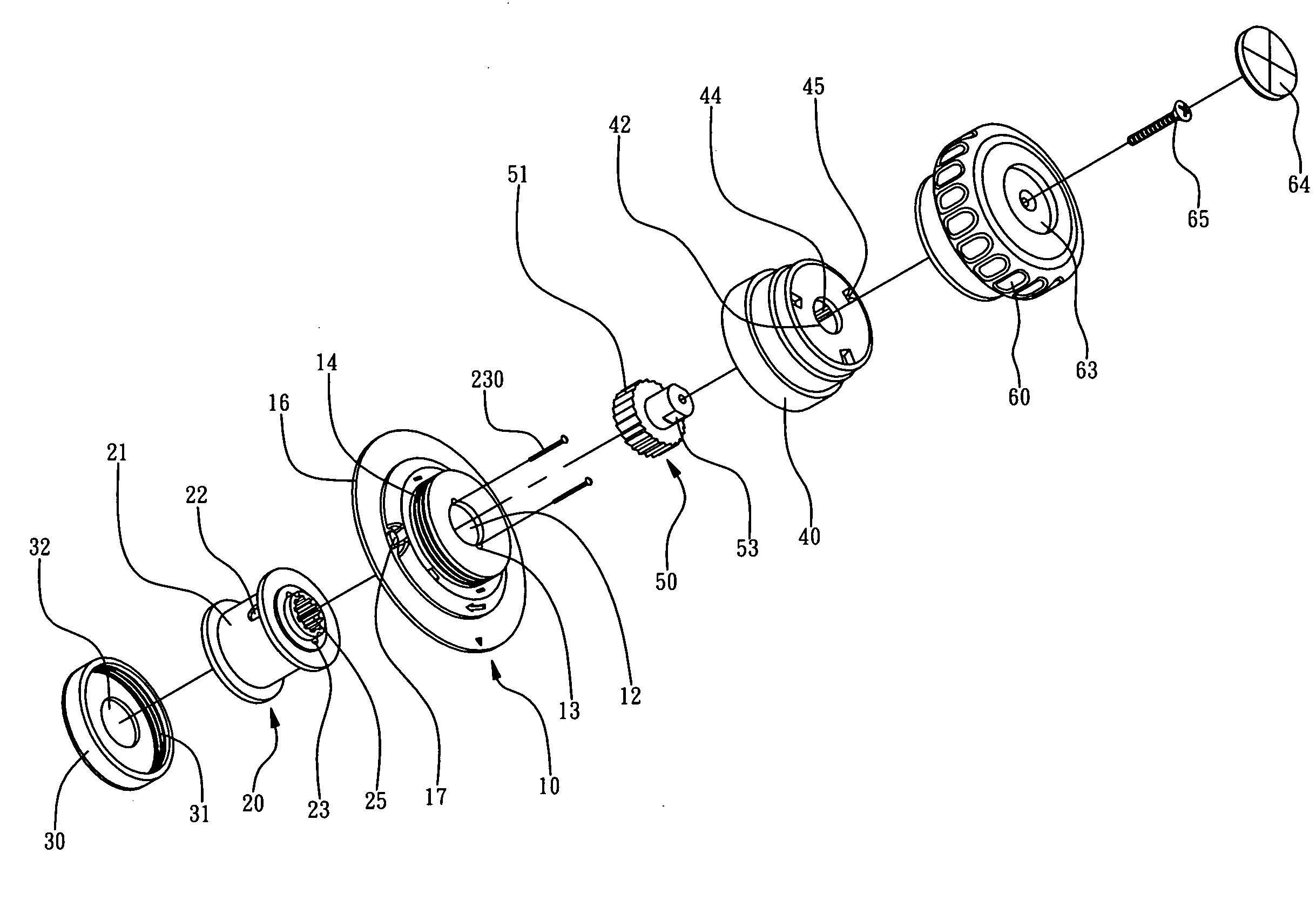
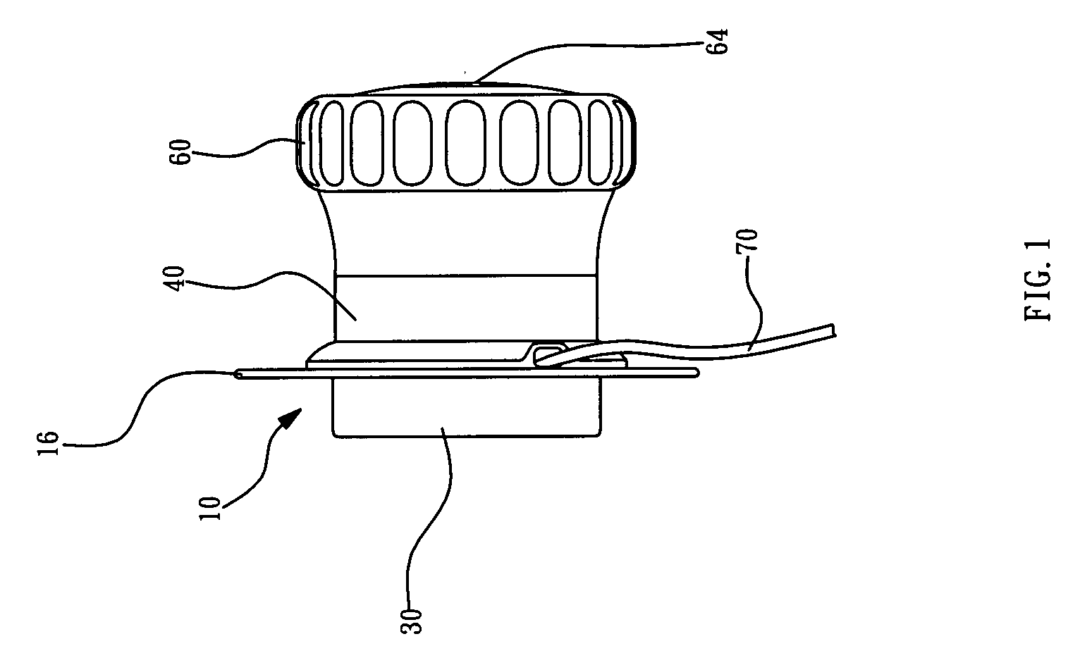
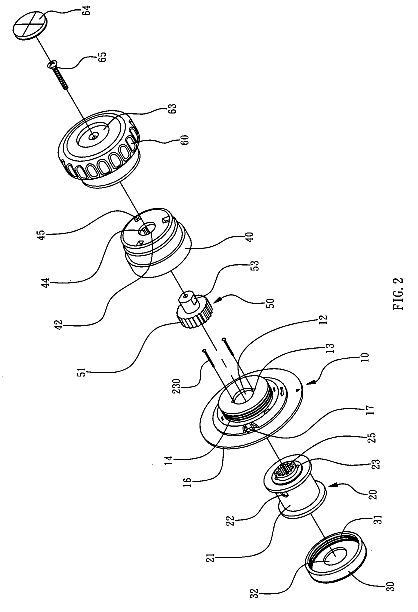
[0025]Referring to the drawings and initially to FIGS. 1-9, a shoelace reel in accordance with the preferred embodiment of the present invention comprises a support seat 10 having a first side formed with an axially extending receiving hole 11 and a periphery formed with two spaced guide holes 17 each connected to the receiving hole 11, a spool 20 rotatably mounted in the receiving hole 11 of the support seat 10 and having a periphery formed with a winding zone 21 and a first end formed with an inner gear 25, a shoelace 70 having two distal ends each extended through a respective guide hole 17 into the receiving hole 11 of the support seat 10 and each secured to the winding zone 21 of the spool 20 to move with the winding zone 21 of the spool 20, a limit sleeve 40 mounted on a second side of the support seat 10 and having an inner wall formed with an axially extending limit hole 41 and a plurality of oneway ratchet teeth 44, and a drive member 50 rotatably and movably mounted in the...


PUM


Abstract

A shoelace reel includes a support seat, a spool rotatably mounted in the support seat, a shoelace having two distal ends each secured to the winding zone of the spool, a limit sleeve mounted on the support seat, a drive member rotatably and movably mounted in the limit sleeve, and a control knob rotatably and movably mounted on the limit sleeve and connected to the drive member. Thus, the user only needs to rotate the control knob to tighten the shoelace and to pull out the control knob to loosen the shoelace. In addition, the user only needs to operate the control knob to tighten or loosen the shoelace, so that the user can tighten or loosen the shoelace by his one hand only.

Description

BACKGROUND OF THE INVENTION[0001]1. Field of the Invention[0002]The present invention relates to a shoelace reel and, more particularly, to a shoelace reel for tightening or loosening a shoelace.[0003]2. Description of the Related Art[0004]A shoelace is mounted on a shoe so as to tighten or loosen the shoe. However, the user has to stretch the shoelace so as to tighten the shoe and to release the shoelace so as to loosen the shoe, thereby causing inconvenience to the user and wasting the user's time when tightening or loosening the shoelace. In addition, the shoelace protrudes from the shoe, thereby decreasing the aesthetic quality of the shoe.BRIEF SUMMARY OF THE INVENTION[0005]In accordance with the present invention, there is provided a shoelace reel, comprising a support seat having a first side formed with an axially extending receiving hole and a periphery formed with two spaced guide holes each connected to the receiving hole, a spool rotatably mounted in the receiving hole o...

Claims


Application Information

Patent Timeline
Patent Type & Authority Applications(United States)
IPC IPC(8): A43C11/00
CPCA43C11/16Y10T24/3724Y10T24/2183A43C11/20A43C11/165
Inventor HU, JUNG-FU
Owner MENG HANN PLASTIC
Why Eureka
Try Eureka