Power source device and battery cooling structure for vehicle

Inactive Publication Date: 2008-08-21
HONDA MOTOR CO LTD
View PDF24 Cites 215 Cited by
  • Summary
  • Abstract
  • Description
  • Claims
  • Application Information

AI Technical Summary

Benefits of technology

[0013]Accordingly, it is a first object of the present invention to protect a battery box of an electric automobile or a

Problems solved by technology

When such a hybrid automobile is subjected to a side collision, it is necessary to protect the battery box from the damage, however, if a special reinforcement for protecting the battery box is provided, there is a problem that the weight of a vehicle body is increased, thus lowering vehicle performance.
A large load is applied from an upper end of a damper of a suspension system, particularly, to the side frame corresponding to a position corresponding to a wheel housing of a rear wheel, but if a power source device is mounted at such a portion, a space for disposition of the cross member is eliminated leading to a possibility that the

Method used


Image

  • Power source device and battery cooling structure for vehicle
  • Power source device and battery cooling structure for vehicle
  • Power source device and battery cooling structure for vehicle

Examples


first embodiment

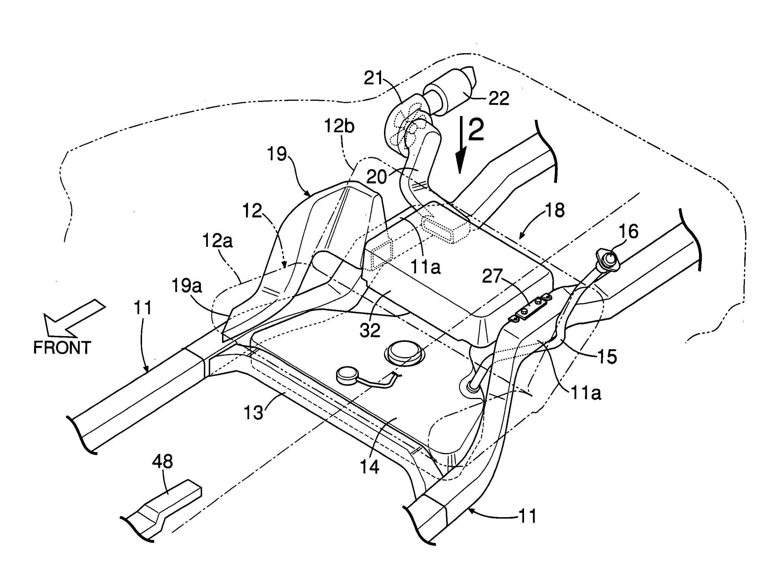
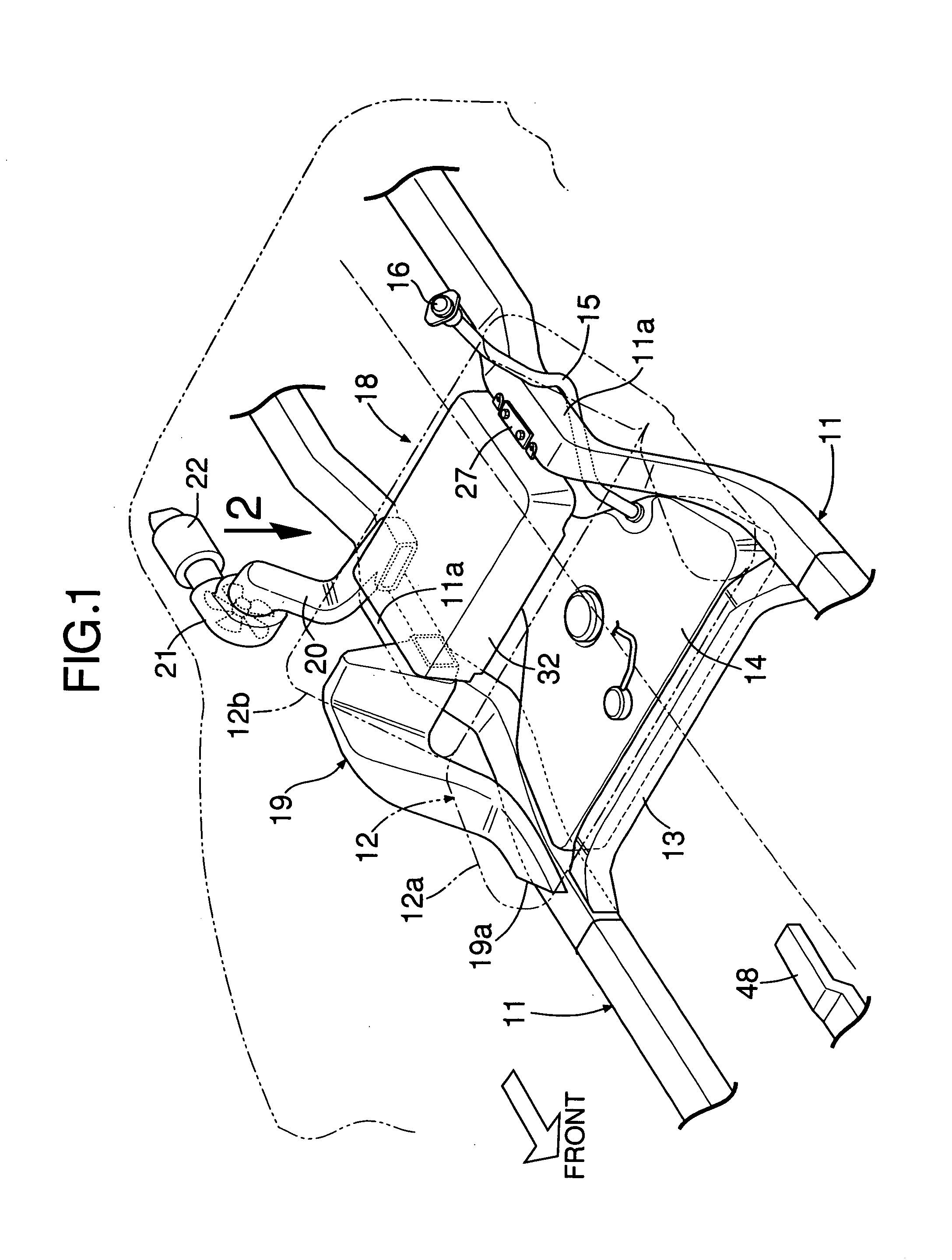
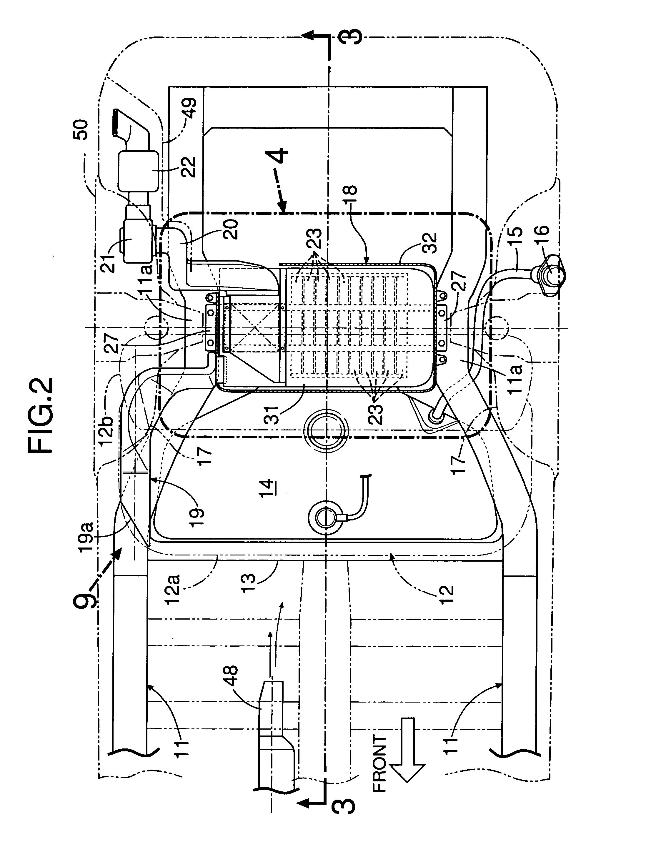
[0072]the present invention will now be described with reference to FIGS. 1 to 11.

[0073]As shown in FIGS. 1 to 4, a hybrid automobile provided with an engine and a motor-generator as driving power sources includes a pair of side frames 11, 11 disposed in a longitudinal direction of a vehicle body on left and right sides of the vehicle body. The left and right side frames 11, 11 are connected to each other by a cross member 13 on a lower surface of a front portion of a seat cushion 12a of a rear seat 12. A fuel tank 14 is disposed in a space surrounded by the left and right side frames 11, 11, the cross member 13 and the lower surface of the seat cushion 12a. A fuel supply port 16 is provided at an upper end of a filler tube 15 extending rearwards and upwards from a left end of the fuel tank 14. The left and right side frames 11, 11 have upward curved portions 11a, 11a provided at locations corresponding to wheel housings 17, 17. A battery box 18 of a power source system for a power ...

second embodiment

[0094]the present invention will now be described with reference to FIGS. 12 to 15B.

[0095]In the above-described first embodiment, the fan 21 is mounted at the downstream end of the exhaust duct 20, but in the second embodiment, a fan 21 is mounted between lower and upper battery covers 30 and 31 of a battery box 18 and a down converter 46 at an upstream end of an exhaust duct 21, as shown in FIGS. 12 to 14.

[0096]The structure of the battery box 18 is simpler than that in the first embodiment; a cooling air introducing port 41 and a communication opening 43 are formed in right end faces of the lower and upper battery covers 30 and 31 of the battery box 18, and a single partition wall 33Ua, 33La is formed within the lower and upper battery covers 30 and 31. An intake duct 19 is connected at its downstream end to the cooling air introducing port 41; an intake passage 21a of the fan 21 such as a sirocco fan is connected to the communication opening 43; and the down converter 46 is disp...


PUM


Abstract

A battery box housing a battery is mounted between left and right side frames extending in a longitudinal direction of a vehicle body so that the battery box is offset to a left side of the vehicle body, and an intake duct and an exhaust duct for cooling air for cooling the battery are connected to an end of the battery box on a right side of the vehicle body. Therefore, it is possible not only to protect the battery between the left and right frames from a shock caused upon a side collision, but also to ensure a space for disposition of the intake duct and the exhaust duct while ensuring a volume of the battery box to the maximum. Moreover, the battery box is connected at its left and right ends to the left and right side frames.

Description

RELATED APPLICATION DATA[0001]The Japanese priority application Nos. 2005-163089 and 2005-358069 upon which the present application is based are hereby incorporated in their entirety herein by reference.BACKGROUND OF THE INVENTION[0002]1. Field of the Invention[0003]The present invention relates to a power source device for supplying an electric power from a battery housed in a battery box to a motor for driving the vehicle, and to a battery cooling structure for cooling the battery by cooling air flowing through a cooling passage provided in the battery box.[0004]2. Description of the Related Art[0005]Japanese Patent Application Laid-open Nos. 2003-317813 and 2005-71759 disclose a battery cooling structure in which a battery box housing a battery for supplying an electric power to a motor-generator for a hybrid automobile is disposed in a front portion of a trunk room provided in the rear of a rear seat, and an intake duct and an exhaust duct for supplying and discharging cooling a...

Claims


Application Information

Patent Timeline
IPC IPC(8): B60R16/04B60K6/28B60K6/40B60K11/06B60K15/01B60L50/64B60R16/02B62D25/20H01M2/10H01M10/50H01M10/60H01M10/613H01M10/617H01M10/625H01M10/6563H01M10/6566
CPCB60K1/04Y02T10/705B60K2001/0416B60L3/0007B60L11/1874B60L11/1877B60L11/1879B60L2240/36H01M2/1077H01M2/1083H01M10/5004H01M10/5016H01M10/5067H01M10/5073H01M10/5097Y02T10/7005B60K2001/005H01M10/625H01M10/6563H01M10/667H01M10/6566H01M10/613B60L58/26B60L50/66B60L50/64Y02T10/70Y02E60/10H01M50/249H01M50/278H01M50/224H01M50/213H01M50/244
Inventor KOIKE, EIJITAKEDOMI, HARUMIOYA, SATOYOSHIOHKUMA, KANAESATO, SEIICHI
Owner HONDA MOTOR CO LTD
Why Eureka
Try Eureka