
Rechargeable Battery Assembly Having Data and Power Connector Plug

a technology of data and power connectors, applied in the direction of secondary cell servicing/maintenance, cell components, cell component details, etc., can solve the problems of general dependency, no approach has presented a mechanical method of providing usb connectors, prior art has not addressed or presented mechanical approaches, etc., to achieve convenient access, reduce length, and compact storage configuration

Inactive Publication Date: 2008-08-21
MOIXA ENERGY HLDG
View PDF9 Cites 8 Cited by
  • Summary
  • Abstract
  • Description
  • Claims
  • Application Information

AI Technical Summary

Benefits of technology

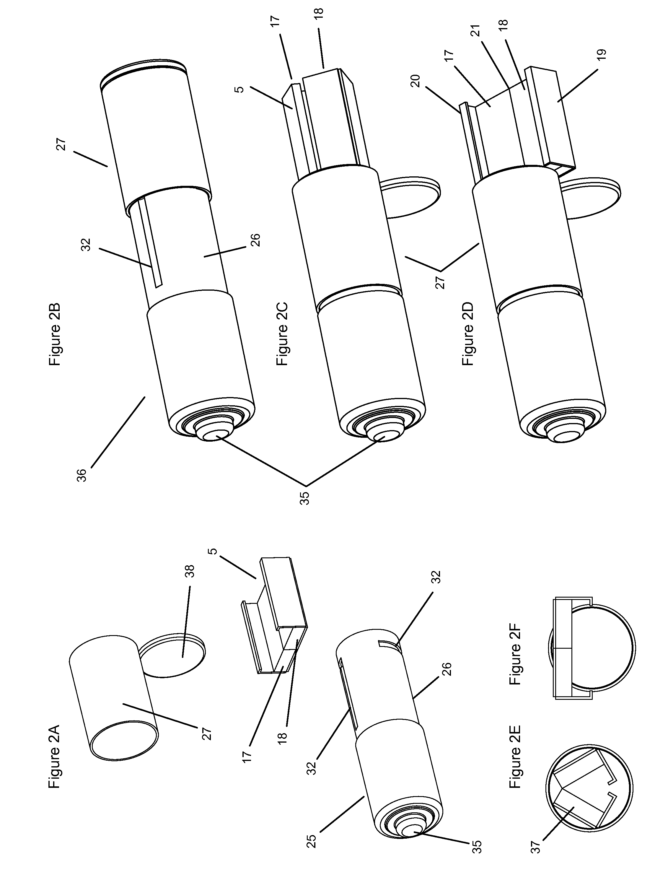
[0010]The connector plug is preferably a USB connector. Alternatively, a FireWire connector or other suitable connector type can be used. The present invention preferably provides a rechargeable battery with integral USB connector that forms a typical and standard small battery format, such as an AAA, AA type or larger format, with a recharge configuration that reveals a USB connector suitable for convenient recharging in a portable or desktop computing device, without the typical geographic problem associated with recharging batteries of carrying a separate recharging adaptor or unit for charging directly in AC mains sockets. The battery therefore provides a universal battery suitable for using in many devices and particularly in computing peripherals, such as input devices, digital music players and cameras. A further advantage of the invention is to provide a rechargeable battery with integral USB in an AA format that can receive a standard rechargeable AAA battery unit providing manufacturing efficiency or the option for a consumer to recharge their individual AAA batteries.
[0011]Preferably, the rechargeable battery unit has a smaller length than said battery assembly, and said connector is located adjacent said rechargeable battery unit and is rigidly supported directly or indirectly by said rechargeable battery unit. The rechargeable battery unit may be a discrete unit provided separately from said connector. Alternatively, the rechargeable battery unit may incorporate at least part of the connector or circuitry or support therefor within the battery unit.
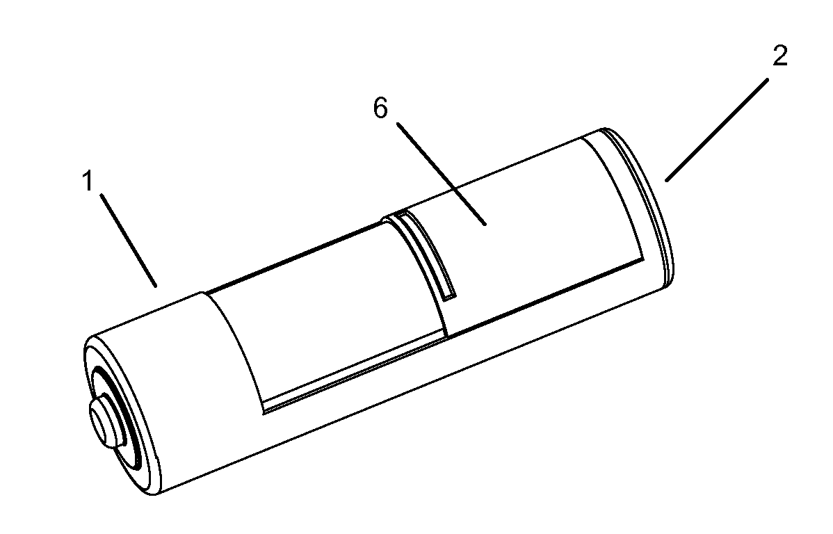
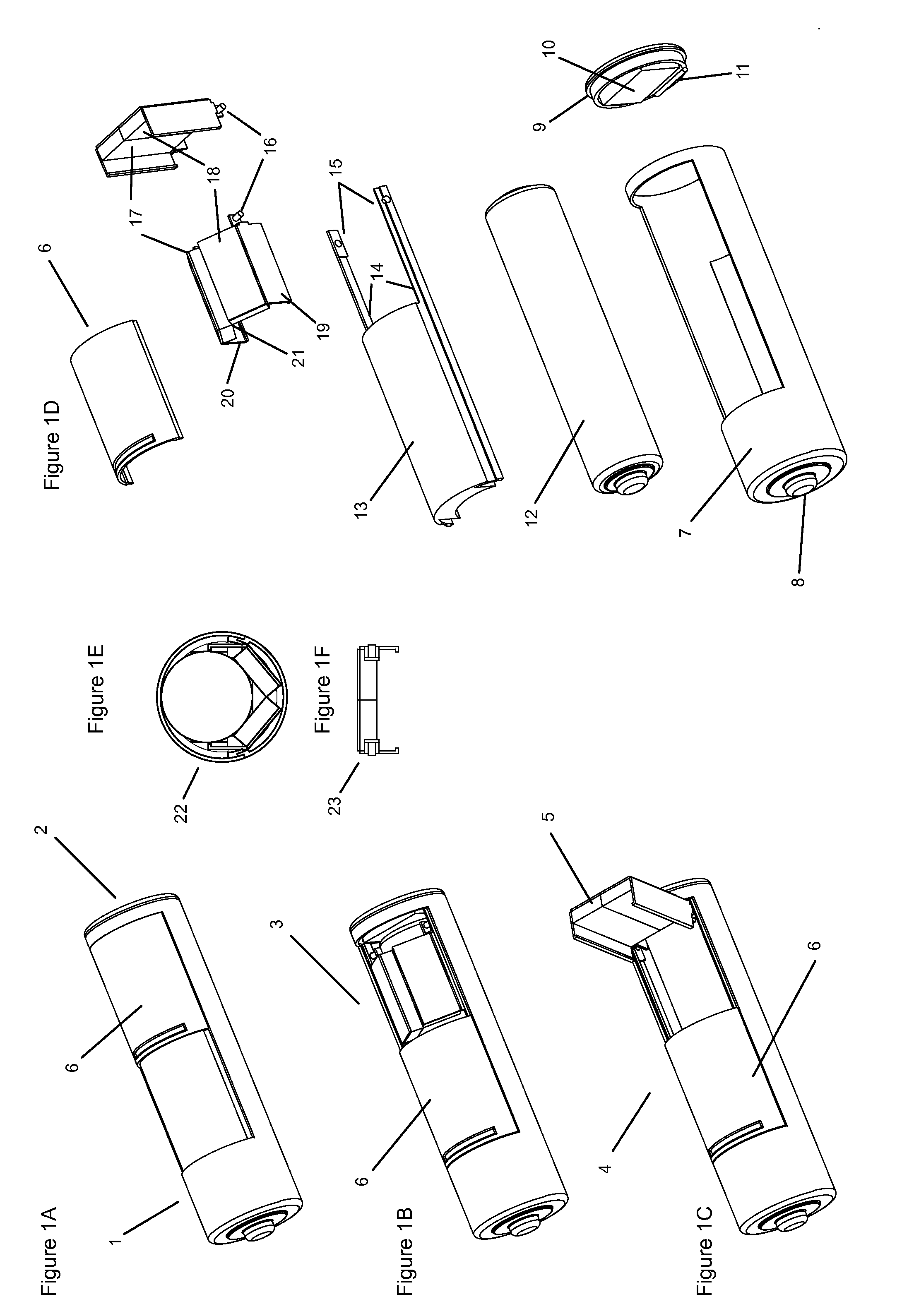
[0012]In a further preferred embodiment the rechargeable battery assembly comprises a cap for covering the data and power connector plug in the deployed configuration. The cap may have a first terminal and the battery assembly may have a second terminal to deliver current to a load connected between the first and second terminals. The cap may have a prong for making an electrical connection between the first terminal and the rechargeable battery unit thus bypassing the connector. The rechargeable battery assembly could be implemented in a compact AA cylindrical format with a sliding outer sub-section or end-cap, and a rigid USB connector that could be either a micro or standard format, and using a reduced length AA type internal battery encased within the overall assembly.
[0013]In one embodiment of the present invention, the rechargeable battery assembly comprises a casing for containing the rechargeable battery unit and the connector. The battery assembly may have at least one terminal formed on a movable section of the battery casing, and the movable section of the battery casing may be movable to make the connector accessible. The connector may be made accessible by sliding a sub-section of the casing relative to the rest of the casing, the sub-section having a hole through which said connector can pass upon said sliding. As an alternative, the connector can be made accessible by sliding a sub-section of the casing relative to the rest of the casing to allow the connector to pivot out of the casing to an accessible position.
[0014]In one embodiment of the present invention, the connector is constructed and arranged to be able to fold between a rigid form suitable for making a said connection when the battery assembly is in said recharge configuration, and a storage form suitable for being accommodated within the envelope of said battery assembly conventional battery format when the battery assembly is in said deployed configuration. The connector may be formed from two units hinged and sprung together along a central axis, where each unit supports a respective power and data connection prong and supports side plates that are sprung hinged or fixed, such that the connector in its rigid form has a partial box-section with rigid sides arranged in a perpendicular fashion.
[0015]The rechargeable battery assembly, of the present invention, in a preferred embodiment comprises an outer case formed to be a regular cylindrical battery format in a deployed or storage configuration, which supports a sliding sub-section, internal recharging circuitry and a folding integral connector that is accessible in the charging configuration. The outer casing may be generally shaped to be AAA or AA format with a standard metallic positive prong at one end and a flat metallic face on the opposite end where the face is directly hinged to the outer casing or may support sprung hinging flaps to allow a connector to protrude in the charging configuration. The integral connector in a preferred configuration is a micro (Series B) or full-size (Series A) USB connector plug comprising two power and two data prongs and is connected to local USB control circuitry to regulate power recharging. The USB connector may preferably be formed as a collapsible sub-assembly by hinging along a central axis and along the metallic edges to allow a more compact storage configuration within an AA or AAA battery. The overall USB assembly may be connected to a folding axis, to enable the USB to rotate for easier access in the charging configuration. The collapsible USB assembly may be formed with a reduced cross-section profile consisting primarily of two sides and a base to reduce the overall storage volume whilst maintaining the ability of locking securely within a respective USB socket. The sliding sub-section in a preferred configuration would consist of a sub-section of the outer shell that can slide relative to the outer casing and may preferably be supported by a shaped section with appropriate rails and grooves.

Problems solved by technology

An ongoing problem with rechargeable batteries is their general dependency on an external recharging unit, plug and AC socket, which are often unavailable when recharging is required.
However, this approach is only appropriate in combination with an external North American plug and AC mains supply so does not address the geographic issue.
However, despite the large volume of granted patents covering various approaches for rechargeable batteries with integral connectors, either as custom devices or devices forming an existing standard format, the prior art has not addressed or presented a mechanical approach of integrating a generic USB or other computer peripheral connector into a small format battery that can form a typical battery in one configuration in which it can be used in an identical way to the standard format battery, and can form a further configuration in which the peripheral connector is exposed and deployed suitable for recharging.
Furthermore, no approach has presented a mechanical method of providing a USB connector in such a manner as to be integrated within a battery assembly, either as a flexible configuration or as a rigid folding configuration or in such a manner as to form a reduced section suitable for fastening within a USB socket.
Similarly no prior art examined has proposed a battery adaptor suitable for converting an AAA battery into a AA format with an integral external connector.

Method used


Image

  • Rechargeable Battery Assembly Having Data and Power Connector Plug
  • Rechargeable Battery Assembly Having Data and Power Connector Plug
  • Rechargeable Battery Assembly Having Data and Power Connector Plug

Examples


embodiment 24

[0082]FIG. 10 shows an AA embodiment 24 formed using a standard reduced length battery cell 25 with front face plate 42 being attached to a moulding 71 that supports the USB assembly 28 and also supports a split folding front cap 27 that opens in two halves. FIG. 10A shows the battery in the standard usage format. FIG. 10B shows the battery with front cap folded back in two halves 76 and 77 by means of hinges 78 attached to moulding 71 where moulding 71 is also seen to support the casing 53 forming the inner layer of the USB 28. FIG. 10C shows an exploded view of components. In this embodiment positive cap 35 supports an alternative shape of prong 52 and hook 51 that connects directly to a positive prong 61 on the USB assembly 29 circuit board and through to prong 74 for connection to the positive terminal which is the front face plate 42 and prong 75 similarly connecting to the negative outer shell 56. Moulding 71 both affixes the USB assembly 53 and connects to face plate 42 on th...

embodiment 36

[0086]FIG. 13 shows an AAA embodiment 36 with a half folding USB connector 83 and hinged folding front cap 27. FIG. 13A shows an exploded view of components where moulding 71, which affixes to rear cell front plate 42, supports one half of the USB connector 83 that itself supports a flexible hinge 82 that joins both halves of the circuit board 83 and 84 together. Circuitry may be embedded under the circuit board and within the moulding 71. The hinge may be biased to prefer a flat open configuration such that the action of opening the front cap and hinging by means of hinge 73 and axle 72 enables the USB circuit to pop open as shown in FIG. 13D and FIG. 13E. The action of folding the front cap closed acts to lock the two halves of the USB folded. The positive prong 52 is suitably shaped to pass outside and underneath the USB plug. In this embodiment no external USB casing 31 is used with the deployed USB connector 83 and 84 being capable of insertion within a normal USB socket.

[0087]...


PUM

PropertyMeasurementUnit
chargeaaaaaaaaaa
chargeaaaaaaaaaa
current valueaaaaaaaaaa

Abstract

A rechargeable battery assembly comprises a rechargeable battery unit and a data and power connector plug. The battery assembly has a deployed configuration in which the battery assembly has the general form of and functions as a conventional battery format, and a recharge configuration in which the data and power connector plug is made accessible to enable said connector to be connected to a suitable receptacle on a computing or peripheral device for recharging of the battery.

Description

CROSS-REFERENCE TO RELATED APPLICATIONS[0001]This application is a continuation from U.S. application Ser. No. 11 / 211,934 filed Aug. 25, 2005, which claims priority from British Patent Application No. 0425967.7 dated 25 Nov. 2004, the content of each of which is hereby incorporated by reference in its entirety for all purposes;STATEMENT REGARDING FEDERALLY SPONSORED RESEARCH OR DEVELOPMENT[0002]Not Applicable.TECHNICAL FIELD OF THE INVENTION[0003]The present invention relates to a rechargeable battery assembly. The invention relates in preferred embodiments generally to a rechargeable battery that has a deployed configuration forming a regular battery format and a collapsed configuration where an integral connector is revealed that can fold out to enable the battery to be plugged into a suitable ‘Bus’ socket on a computing device for recharging, such as a standard or miniature USB (‘Universal Serial Bus’) connector socket. Preferred battery formats are generally cylindrical AAA, AA,...

Claims


Application Information

Patent Timeline
Patent Type & Authority Applications(United States)
IPC IPC(8): H02J7/00H01M50/247H01M50/543
CPCH01M2/105H01M10/48H01M10/44H01M10/4257Y02E60/10H01M50/213H01M10/46
Inventor DANIEL, SIMON R.WRIGHT, CHRISTOPHER V.
Owner MOIXA ENERGY HLDG
Learn More