
Suspension for a hard disk drive microactuator

a microactuator and hard disk drive technology, applied in the direction of magnetic recording, data recording, instruments, etc., can solve the problem of affecting the quantity of data recorded on the surface of the disk

Inactive Publication Date: 2008-08-21
HITACHI GLOBAL STORAGE TECH NETHERLANDS BV
View PDF16 Cites 52 Cited by
  • Summary
  • Abstract
  • Description
  • Claims
  • Application Information

AI Technical Summary

Benefits of technology

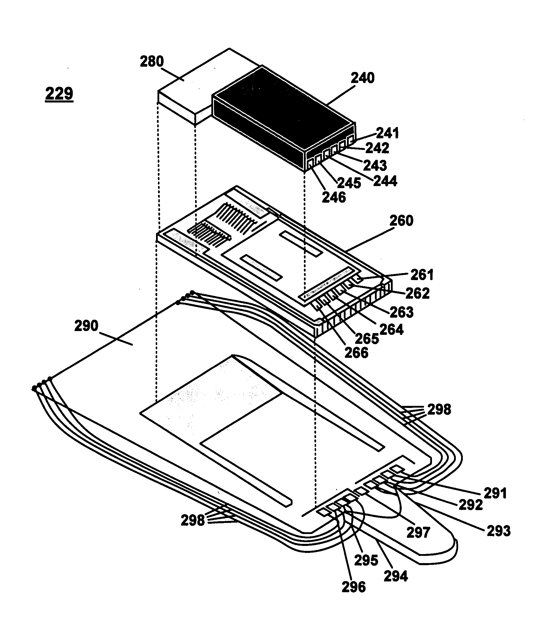
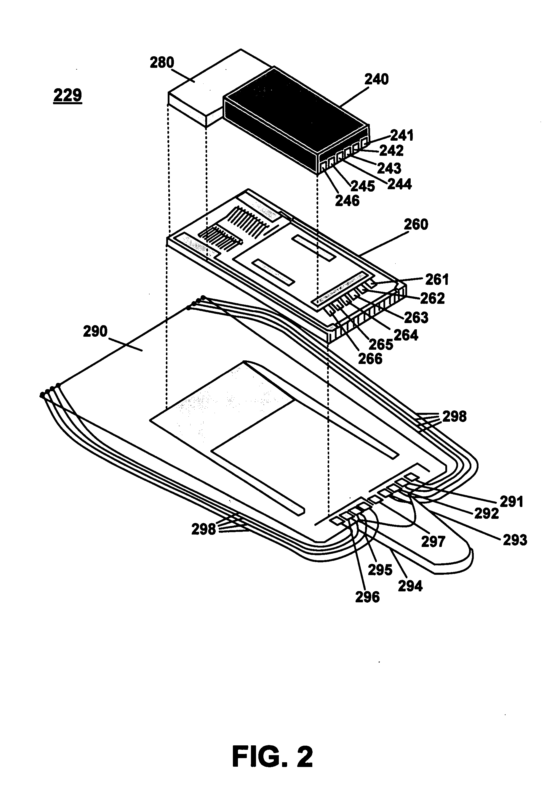
[0009]A disk drive flexure is provided. The disk drive flexure includes a first surface for coupling with a microactuator, the microactuator comprising a moving portion and a stationary portion wherein the moving portion and the stationary portion are integrated within a substrate and wherein the stationary portion is coupled to the first surface by an adhesive. The disk drive flexure further includes a spacer portion for maintaining a distance between the microactuator and the flexure such that the moving portion does not contact the flexure and wherein the spacer portion prevents the adhesive from contacting the moving portion of the microactuator.

Problems solved by technology

Vibration or unwanted relative motion between the slider and surface of disk will affect the quantity of data recorded on the surface of the disk.

Method used


Image

  • Suspension for a hard disk drive microactuator
  • Suspension for a hard disk drive microactuator
  • Suspension for a hard disk drive microactuator

Examples


Embodiment Construction

[0019]Reference will now be made in detail to embodiment(s) of the present invention. While the invention will be described in conjunction with the embodiment(s), it will be understood that they are not intended to limit the invention to these embodiments. On the contrary, the invention is intended to cover alternatives, modifications and equivalents, which may be included within the spirit and scope of the invention as defined by the appended claims.

[0020]Furthermore, in the following detailed description of the present invention, numerous specific details are set forth in order to provide a thorough understanding of the present invention. However, it will be recognized by one of ordinary skill in the art that the present invention may be practiced without these specific details. In other instances, well known methods, procedures, and components have not been described in detail as not to unnecessarily obscure aspects of the present invention.

[0021]The discussion will begin with an...


PUM

PropertyMeasurementUnit
heightaaaaaaaaaa
heightaaaaaaaaaa
distanceaaaaaaaaaa

Abstract

A disk drive flexure is provided. The disk drive flexure includes a first surface for coupling with a microactuator, the microactuator comprising a moving portion and a stationary portion wherein the moving portion and the stationary portion are integrated within a substrate and wherein the stationary portion is coupled to the first surface by an adhesive. The disk drive flexure further includes a spacer portion for maintaining a distance between the microactuator and the flexure such that the moving portion does not contact the flexure and wherein the spacer portion prevents the adhesive from contacting the moving portion of the microactuator.

Description

TECHNICAL FIELD[0001]The invention relates to the field of hard disk drive development.BACKGROUND ART[0002]Direct access storage devices (DASD) have become part of everyday life, and as such, expectations and demands continually increase for greater speed for manipulating and for holding larger amounts of data. To meet these demands for increased performance, the mechano-electrical assembly in a DASD device, specifically the Hard Disk Drive (HDD) has evolved to meet these demands.[0003]Advances in magnetic recording heads as well as the disk media have allowed more data to be stored on a disk's recording surface. The ability of an HDD to access this data quickly is largely a function of the performance of the mechanical components of the HDD. Once this data is accessed, the ability of an HDD to read and write this data quickly is a primarily a function of the electrical components of the HDD.[0004]A computer storage system may include a magnetic hard disk(s) or drive(s) within an ou...

Claims


Application Information

Patent Timeline
Patent Type & Authority Applications(United States)
IPC IPC(8): G11B5/56
CPCG11B5/5552G11B5/4833
Inventor HIRANO, TOSHIKITAKAHASHI, HARUHIDE
Owner HITACHI GLOBAL STORAGE TECH NETHERLANDS BV
Learn More