Housing Structure of Acoustic Controller

Inactive Publication Date: 2008-08-21
YAMAHA CORP
View PDF9 Cites 3 Cited by
  • Summary
  • Abstract
  • Description
  • Claims
  • Application Information

AI Technical Summary

Benefits of technology

[0009]The present invention provides a housing structure of an acoustic controller capable of inc

Problems solved by technology

The acoustic controller disclosed in Japanese Design Registration No. 1256520, however, has a drawback that the efficiency of heat radiation becomes low when rack-mounted because of a small distance from the heat radiation openings of the housing to side walls of the rack.
The above described prior art acoustic controller having heat radiation openings formed in the housing bottom surface also has a drawback that heat radiation efficiency is lowered when the controller is stationarily placed on a tabletop surface so that the distance

Method used


Image

  • Housing Structure of Acoustic Controller
  • Housing Structure of Acoustic Controller
  • Housing Structure of Acoustic Controller

Examples


Example

[0034]The present invention will now be described in detail below with reference to the drawings showing a preferred embodiment thereof.

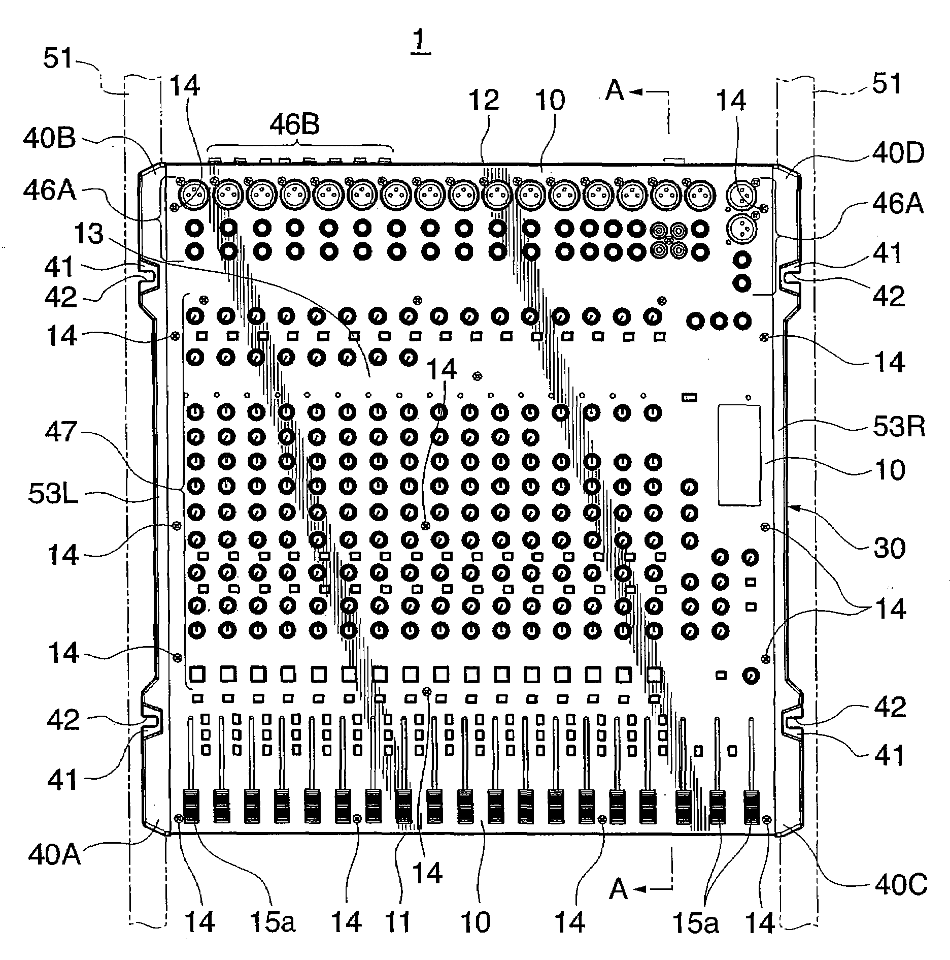
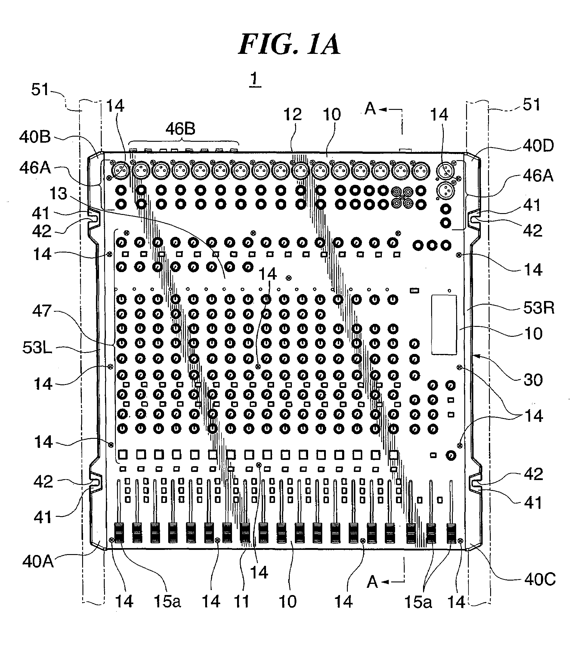
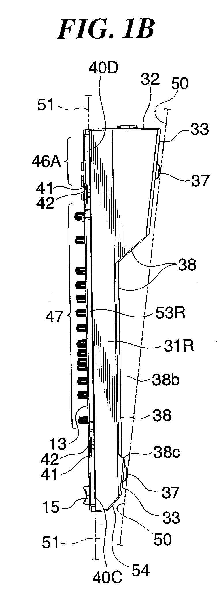
[0035]FIGS. 1A and 1B respectively show in plan view and right side view an acoustic controller to which a housing structure according to one embodiment of this invention is applied. The acoustic controller 1 is configured as a so-called mixer apparatus, and includes a housing comprised of an upper unit 10 and a lower case 30, which are adapted to be assembled together.

[0036]The acoustic controller 1 is configured to be usable in either state of being stationarily placed on a flat surface of a floor, a tabletop or the like (hereinafter referred to as “in stationarily placed state” or “in stationary use”) or being mounted to a rack 51 (hereinafter referred to as “in rack-mounted state” or “in rack mount use”).

[0037]In the following, unless otherwise specified, the vertical direction of the acoustic controller 1 is determined under an assumption that ...


PUM


Abstract

A housing structure of an acoustic controller, in which a lower case of the controller has an increased rigidity and improved moldability. The lower case is integrally formed by a resin and has a bottom surface thereof disposed to face a tabletop surface when the controller is in a stationarily placed thereon. The bottom surface of the lower case is formed to have a concave-forming portion that defines a concave space communicating with the outside of the controller on the left and right sides thereof and which is upward convex as viewed when the controller is stationarily placed, thus increasing the rigidity of the lower case. Bosses and vertical ribs formed to project upward from a horizontal part of the concave-forming portion of the lower case each have a reduced height, thereby improving the moldability of the lower case.

Description

BACKGROUND OF THE INVENTION[0001]1. Field of the Invention[0002]The present invention relates to a housing structure of an acoustic controller, and more particularly, to a housing structure of an acoustic controller that makes the controller usable both in a stationarily placed state and in a rack-mounted state.[0003]2. Description of the Related Art[0004]Conventionally, there has been known an acoustic controller such as a mixer apparatus that can be used both in a state stationarily placed on a flat surface such as tabletop surface, desktop surface, and floor surface and in a state mounted on a rack. Since there are disposed circuit boards or other heat generating component parts in an acoustic controller housing, the interior of the housing must be cooled.[0005]Japanese Design Registration No. 1256520, for example, discloses an acoustic controller in which heat radiation openings are formed in side walls of the housing for cooling the interior of the housing. Also known is an aco...

Claims


Application Information

Patent Timeline
IPC IPC(8): H05K7/20
CPCH05K7/20545H04H60/04
Inventor WATANABE, TSUTOMUNAGAI, HISASHI
Owner YAMAHA CORP
Why Eureka
Try Eureka