Linear guide apparatus and rolling elements accommodation belt

Inactive Publication Date: 2008-08-21
NSK LTD
View PDF7 Cites 3 Cited by
  • Summary
  • Abstract
  • Description
  • Claims
  • Application Information

AI Technical Summary

Benefits of technology

[0020]Then, the invention has been made with a view to solving the problems in the related art, and a principal object thereof is to provide a novel linear guide apparatus and a rolling elements accommodation belt applied thereto which can s

Problems solved by technology

As a result of this, in some cases, operation noise is increased or propagation of wear of the rolling element is quickened.
However, since the gap is intentionally configured to be provided between the facing end portions of the rolling elements accommodation belt, repetitive tensile force is applied to the rolling elements accommodation belt in addition to repetitive bending.
In particular, when the rolling elements accommodation belt is circulated at high speeds, the circulation resistance of the rolling elements and the rolling elements accommodation belt is increased largely due to viscous drag or the like, and since an excessively large repetitive tensile force is applied to the rolling elements accommodation belt, it is difficult to obtain a sufficient durability.
Consequently, since the distal ends

Method used


Image

  • Linear guide apparatus and rolling elements accommodation belt
  • Linear guide apparatus and rolling elements accommodation belt
  • Linear guide apparatus and rolling elements accommodation belt

Examples


first embodiment

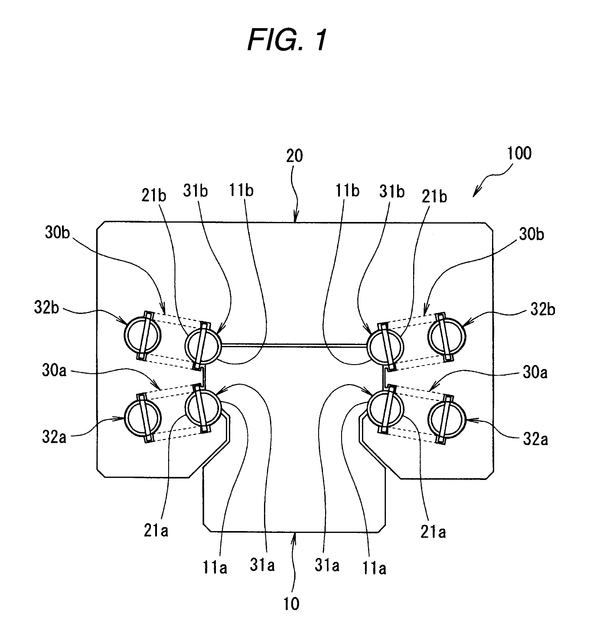
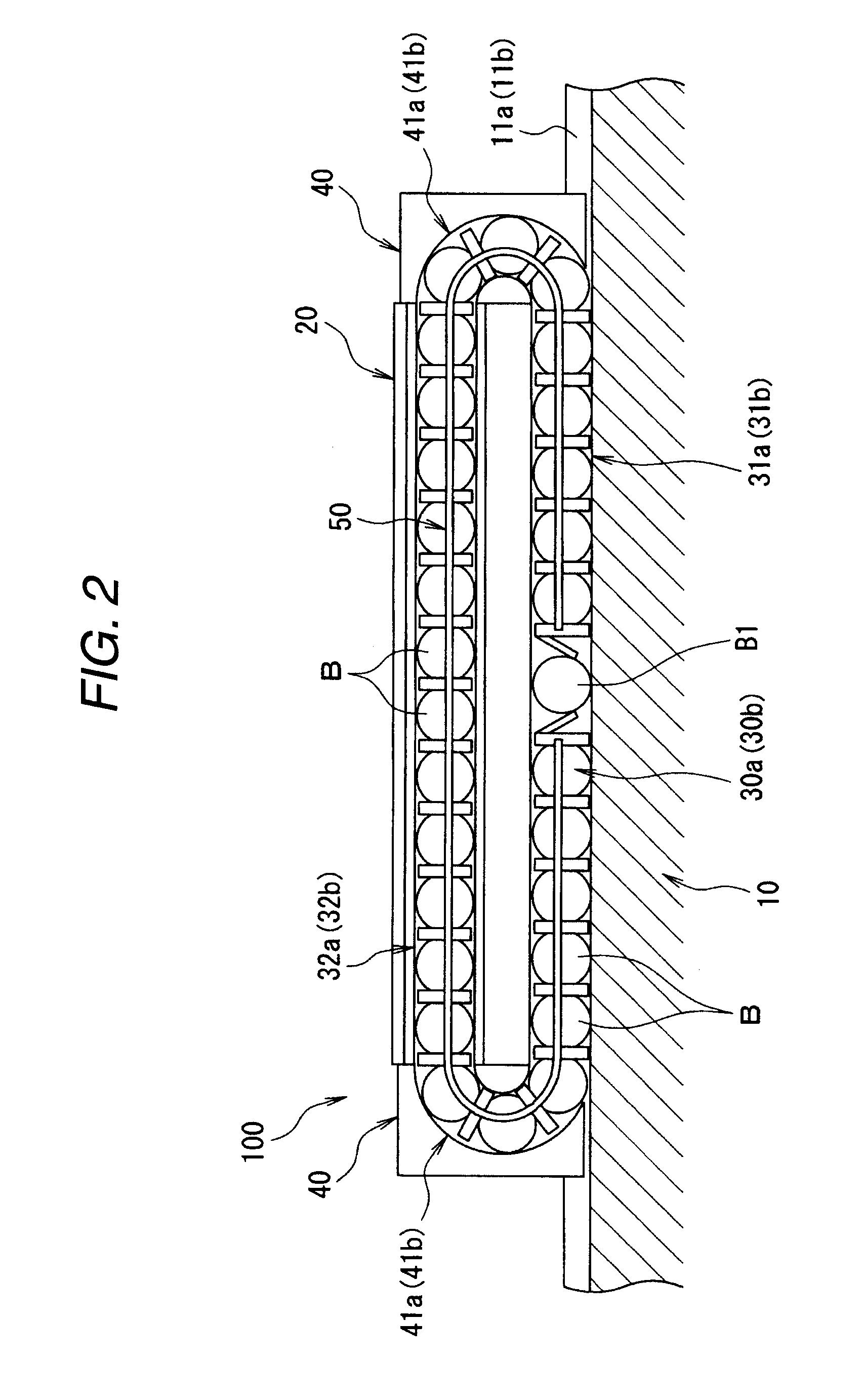
[0075]Firstly, FIGS. 1 to 4 show a first embodiment of a linear guide apparatus 100 according to the invention.

[0076]As shown in FIGS. 1 and 2, the linear guide apparatus 100 is made up, mainly, of a guide rail 10 which extends linearly and a slider 20 which has a downwardly oriented U-shaped cross section and which is brought into sliding engagement with the guide rail 10 so as to straddle the rail.

[0077]This guide rail 10 is formed of a metallic material which is formed into a square shape in cross section, and lower rolling element raceway surfaces 11a, 11a are formed, respectively, on both side surfaces of the guide rail 10 so as to extend continuously along a longitudinal direction thereof.

[0078]On the other hand, slider-side lower rolling element raceway surfaces 21a, 21a are formed, respectively, on both inner side portions of the slider 20 so as to face the lower rolling element raceway surfaces 11a, 11a of the guide rail 10, respectively. Lower rolling element rolling paths...

second embodiment

[0096]Next, FIGS. 5 to 8 show a second embodiment of the linear guide apparatus 100 according to the invention, and like reference numerals will be given to like portions to those of the first embodiment, so as to omit the repetition of similar descriptions.

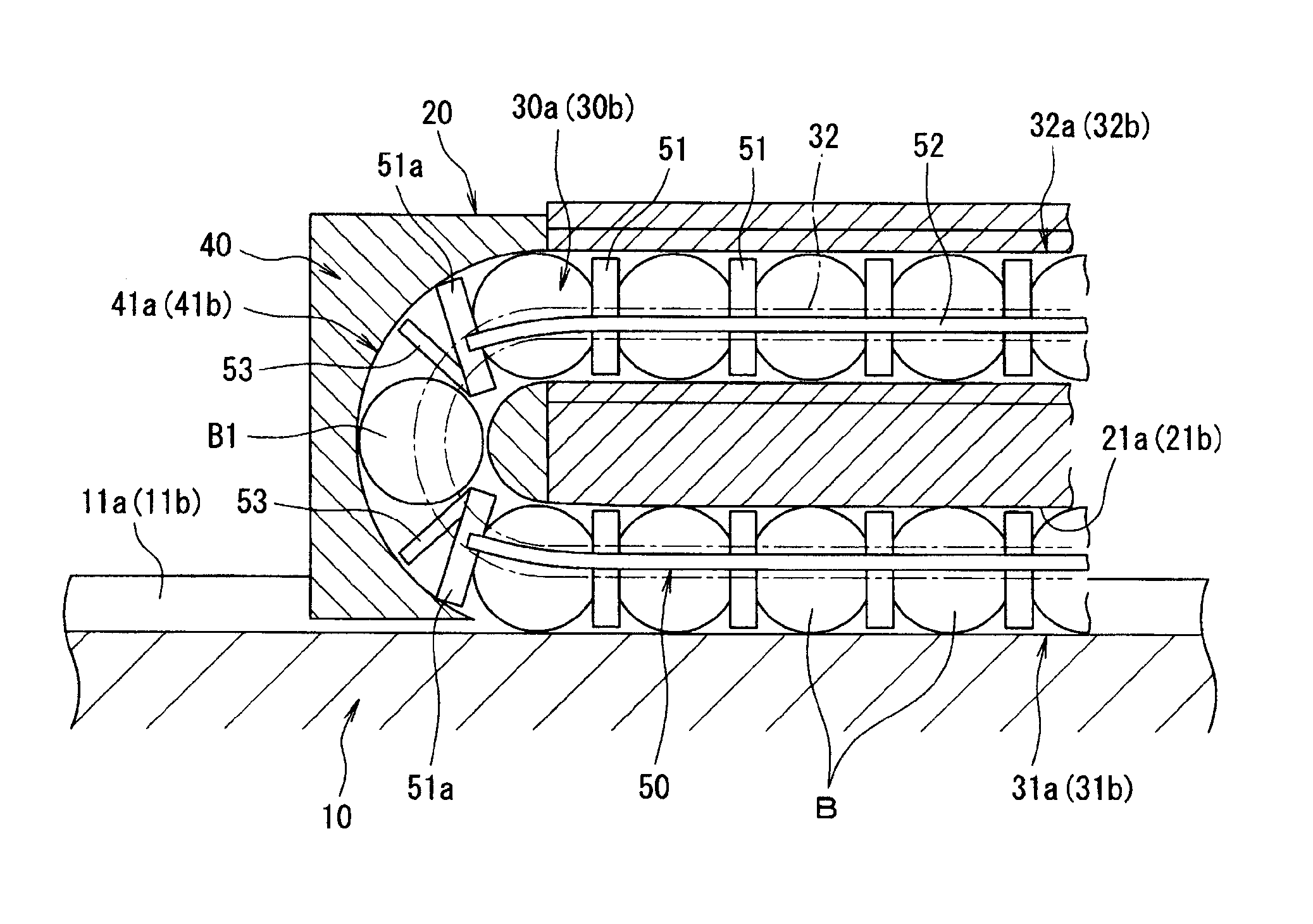
[0097]As shown in the figures, in this embodiment, as in the case of the first embodiment, as a cantilever-shaped, elastically deformable projection 53 at each of end portions of a rolling elements accommodation belt 50 which is disposed in each of rolling element circulation paths 30a, 30a, 30b, 30b, a hook-like projection 53 is provided which is made up of a joint portion 53a which projects in a longitudinal direction from an end face of a spacer 51a at an end face of the belt and a rolling element contact portion 53b which continues from the joint portion 53a and extends from an outer circumferential side towards an inner circumferential side of each of the rolling element circulation paths 30a, 30a, 30b, 30b.

[0098]Then, in a...

third embodiment

[0102]Next, FIGS. 9 and 10 shows a third embodiment of the linear guide apparatus 100 of according to the invention, which is a modified example made to the second embodiment. In addition, like reference numerals will be given to like portions to those of the first and second embodiments, so as to omit the repetition of similar descriptions.

[0103]As shown in the figures, in this embodiment, as in the case of the second embodiment, as a cantilever-shaped, elastically deformable projection 53 at each of end portions of a rolling elements accommodation belt 50, a hook-like projection 53 is provided which is made up of a joint portion 53a which projects in a longitudinal direction from an end face of a spacer 51a at an end face of the belt and a rolling element contact portion 53b which continues from the joint portion 53a and extends from an outer circumferential side towards an inner circumferential side of each of the rolling element circulation paths 30a, 30a, 30b, 30b. In particula...


PUM


Abstract

A linear guide apparatus includes a plurality of a rolling elements which circulates within a rolling element circulation path at predetermined intervals, spacers disposed between the respective rolling elements and a rolling elements accommodation belt which accommodates the rolling elements, connects each of the spacers and has ends thereof. At least one rolling element is disposed between the ends of the rolling elements accommodation belt, a cantilever-shaped elastically deformable projection is provided on an end face of the spacer situated at the end of the rolling elements accommodation belt, the projection projects from an inner circumferential side towards an outer circumferential side of the rolling element circulation path and the projection is inclined relative to an external end face of the spacer at the end of the rolling elements accommodation belt.

Description

BACKGROUND OF THE INVENTION[0001]1. Field of the Invention[0002]The present invention relates to a linear guide apparatus employed on various types of machines such as manufacturing apparatus, working machines and measuring equipment and a rolling elements accommodation belt which is applied to the linear guide apparatus.[0003]2. Description of Related Art[0004]A linear guide apparatus which guides a guided member in a straight line while causing a plurality of rolling elements to circulate in an interior thereof is an apparatus which includes a slider supported on a guide rail so as to travel in an axial direction by virtue of rolling of a plurality of rolling elements provided within a rolling element rolling path formed between a rail-side rolling element raceway surface and a slider-side rolling element raceway surface provided so as to face each other.[0005]In addition, this linear guide apparatus includes an endless rolling element circulation path in which the rolling element...

Claims


Application Information

Patent Timeline
IPC IPC(8): F16C29/06
CPCF16C33/3825F16C29/0647
Inventor MIZUMURA, YOSHINORIXU, WEI
Owner NSK LTD
Why Eureka
Try Eureka