Connector for a flexible flat cable

a flexible flat cable and connector technology, applied in the direction of connection, electrical apparatus, coupling device connection, etc., can solve the problem of still connecting the connector for the flexible flat cable, achieve the effect of preventing fatigue, greatly enhancing the coupling strength of the clamping seat and the locking member, and preventing disengagemen

Inactive Publication Date: 2008-08-21
CVILUX CORP
View PDF2 Cites 6 Cited by
  • Summary
  • Abstract
  • Description
  • Claims
  • Application Information

AI Technical Summary

Benefits of technology

[0010]The primary objective of the present invention is to provide a connector for a flexible flat cable, which can utilize a special retaining member to prevent a fatigue after repeated operations, and by way of a positioning and anti-shaking structure, the coupling strength of a clamping seat and a locking member can be greatly enhanced so as to prevent a disengagement.

Problems solved by technology

However, such a conventional connector for a flexible flat cable still has the following defects that could be improved:
1. The clamping seat is employ the retaining members at two sides thereof to retain the locking member, yet such a retaining structure will cause a fatigue due to repeated operations, because the size of the groove is more than that of the outer side of the clamping seat, and the space of the groove is too small to obtain a sufficient rebounding force.

Method used


Image

  • Connector for a flexible flat cable
  • Connector for a flexible flat cable
  • Connector for a flexible flat cable

Examples


Embodiment Construction

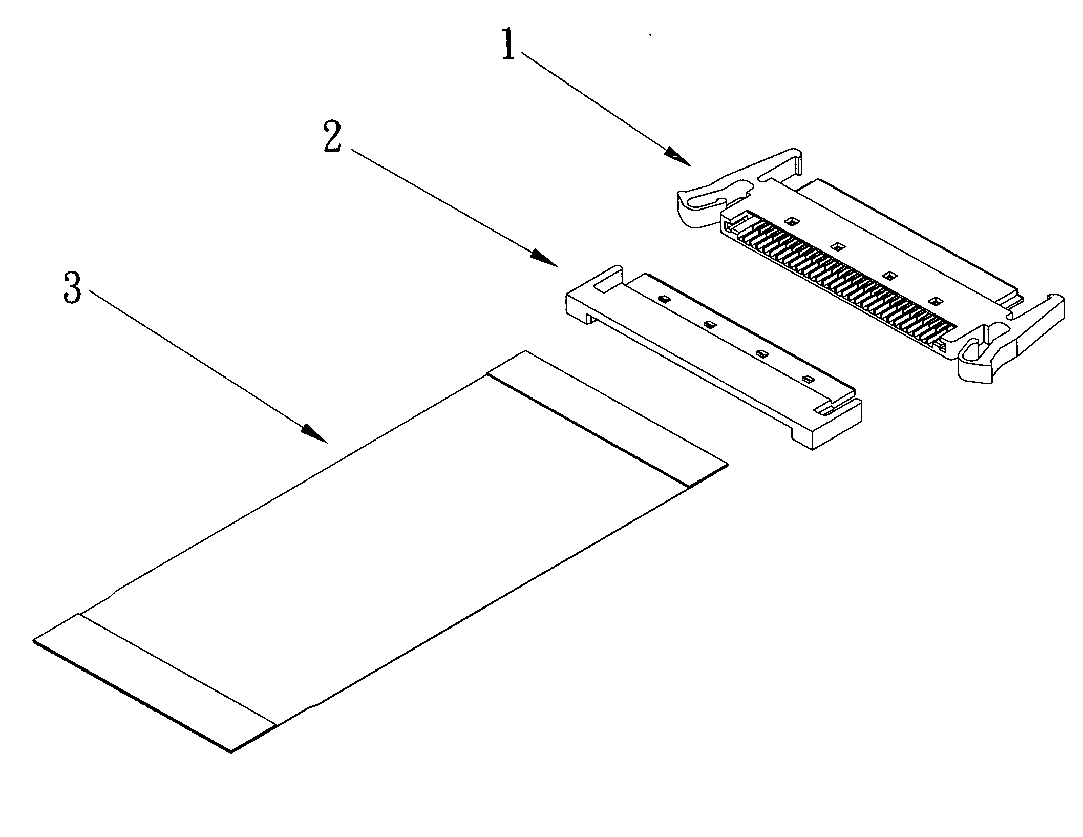
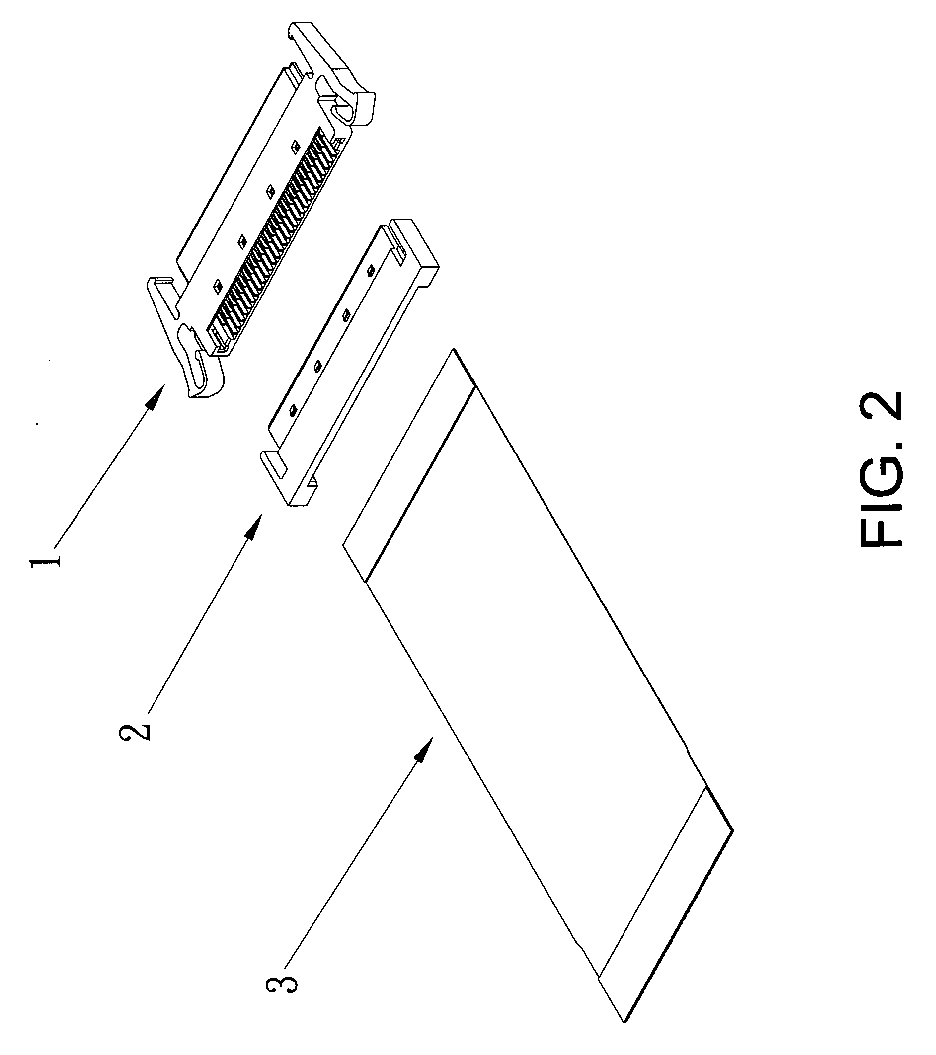
[0021]Referring to FIG. 2, a connector for a flexible flat cable in accordance with the present invention is shown and comprises a clamping seat 1, a locking member 2 and a flexible flat cable 3.

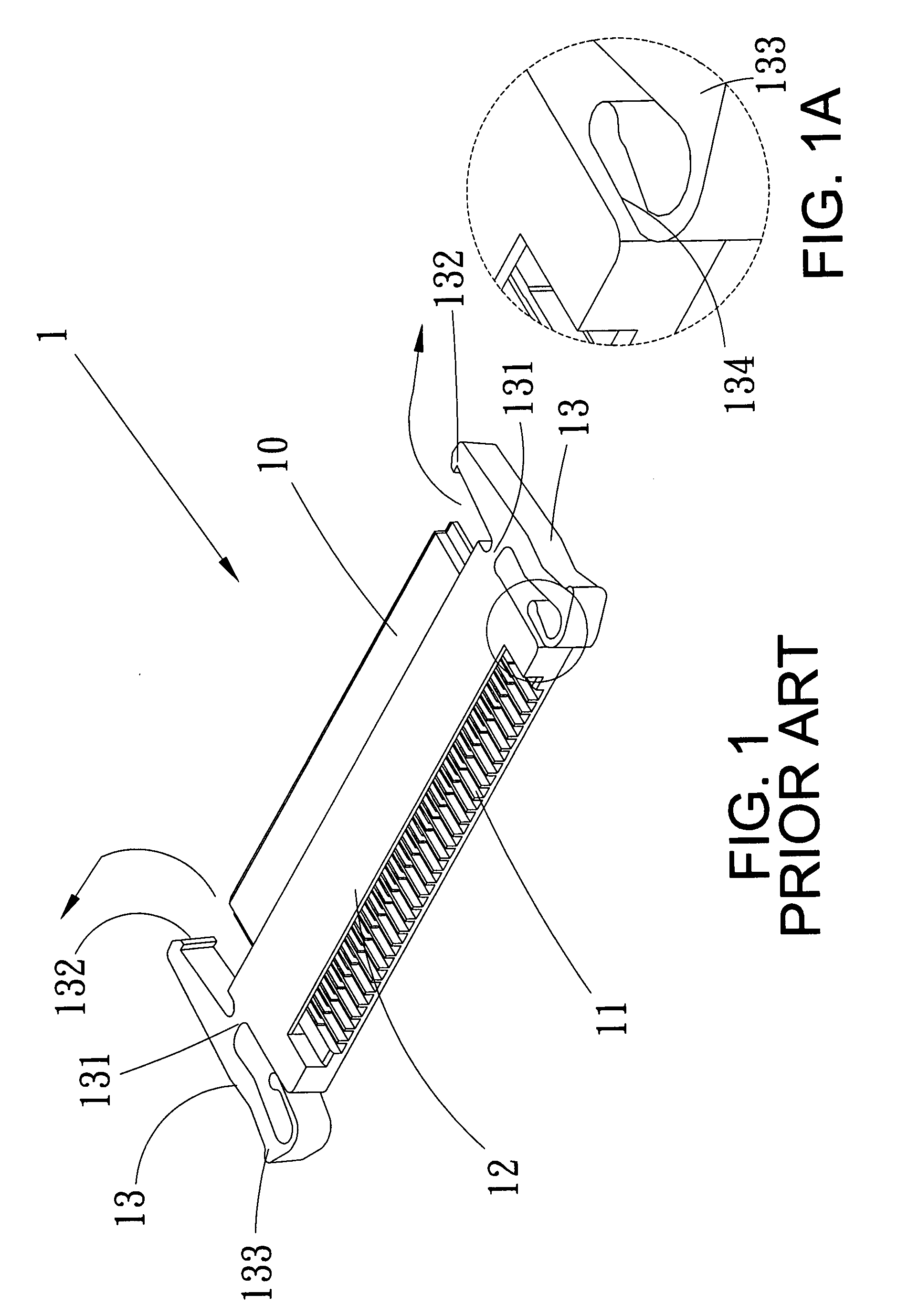
[0022]As shown in FIGS. 3 and 3A, the clamping seat 1 is provided at the front end thereof with an insertion 10 and at the rear end thereof with a plurality of terminal recesses 11 and a cover plate 12, at each of the outer walls of two of the terminal recesses 11, which are located at the leftmost and rightmost sides respectively, is formed a slot 111, on the cover plate 12 are disposed a plurality of bores 121, and at two sides of the clamping seat 1 are respectively arranged a retaining member 13. It is to be noted that the retaining member 13 is connected to the clamping seat 1 by using a connecting portion 131 in its intermediate projected section, and is provided at the front end thereof with a hook 132 and at the rear end thereof with a bent end wall 133, the size of which is less tha...


PUM


Abstract

A connector for a flexible flat cable comprises a clamping seat provided at the front and rear ends thereof with an insertion, terminal recesses and a cover plate respectively, at each of the outer walls of two of the terminal recesses, which are located at the leftmost and rightmost sides, is formed a slot, and on the cover plate being disposed bores, at each of two sides of the clamping seat being arranged a retaining member, a locking member defined at the front end thereof with an inserting segment and snap-on tabs; wherein the retaining member is connected to the clamping seat by using a connecting portion in its intermediate projected section, and is provided at its front and rear ends with a hook and a bent end wall respectively, a groove is formed for spacing the retaining member and the outer side of the clamping seat apart, thereby achieving a secure retaining purpose and preventing the operational fatigue.

Description

BACKGROUND OF THE INVENTION[0001]1. Field of the Invention[0002]The present invention relates to a connector, and more particularly to a connector for a flexible flat cable that can prevent an imperfect contact because of the shaking thereof.[0003]2. Description of the Prior Arts[0004]Generally, electric connector is applied on the electronic products, for example, a connector for a flexible flat cable is used for a transmitting medium of electronic signal.[0005]Referring to FIGS. 1 and 1A, a conventional connector for a flexible flat cable includes a clamping seat 1 provided at the front end thereof with an insertion 10 and at the rear end thereof with a plurality of terminal recesses 11 and a cover plate 12, and at each of two sides of the clamping seat 1 is arranged a retaining member 13 which is connected to the clamping seat 1 by using a connecting portion 131 in its intermediate projected section and is provided at the front end thereof with a hook 132 and at the rear end ther...

Claims


Application Information

Patent Timeline
Patent Type & Authority Applications(United States)
IPC IPC(8): H01R12/24
CPCH01R13/5812H01R12/592
Inventor HUANG, ALEXTSAI, DAVID
Owner CVILUX CORP
Why Eureka
Try Eureka