Micro-needle and micro-needle patch
a micro-needle and patch technology, applied in the field of micro-needle patch, can solve the problems of difficult control of the degree of penetration and easy removal of applied drugs from the surface of the skin, and achieve the effect of easy insertion into the living body
- Summary
- Abstract
- Description
- Claims
- Application Information
AI Technical Summary
Benefits of technology
Problems solved by technology
Method used
Image
Examples
example 1
[0098]FIGS. 15 to 20 are sectional views schematically showing structures of micro-needles employed in Example 1. Each of the micro-needles 121 shown in FIGS. 15 to 20 has a shape tapering down from one end to another end, and all the cross sections thereof perpendicular to the Z direction are circular. Each of the micro-needles 121 shown in FIGS. 15 to 17 has a symmetry axis parallel with the Z direction. On the other hand, each of the micro-needles 121 shown in FIGS. 1 to 20 does not have a symmetry axis parallel with the Z direction.
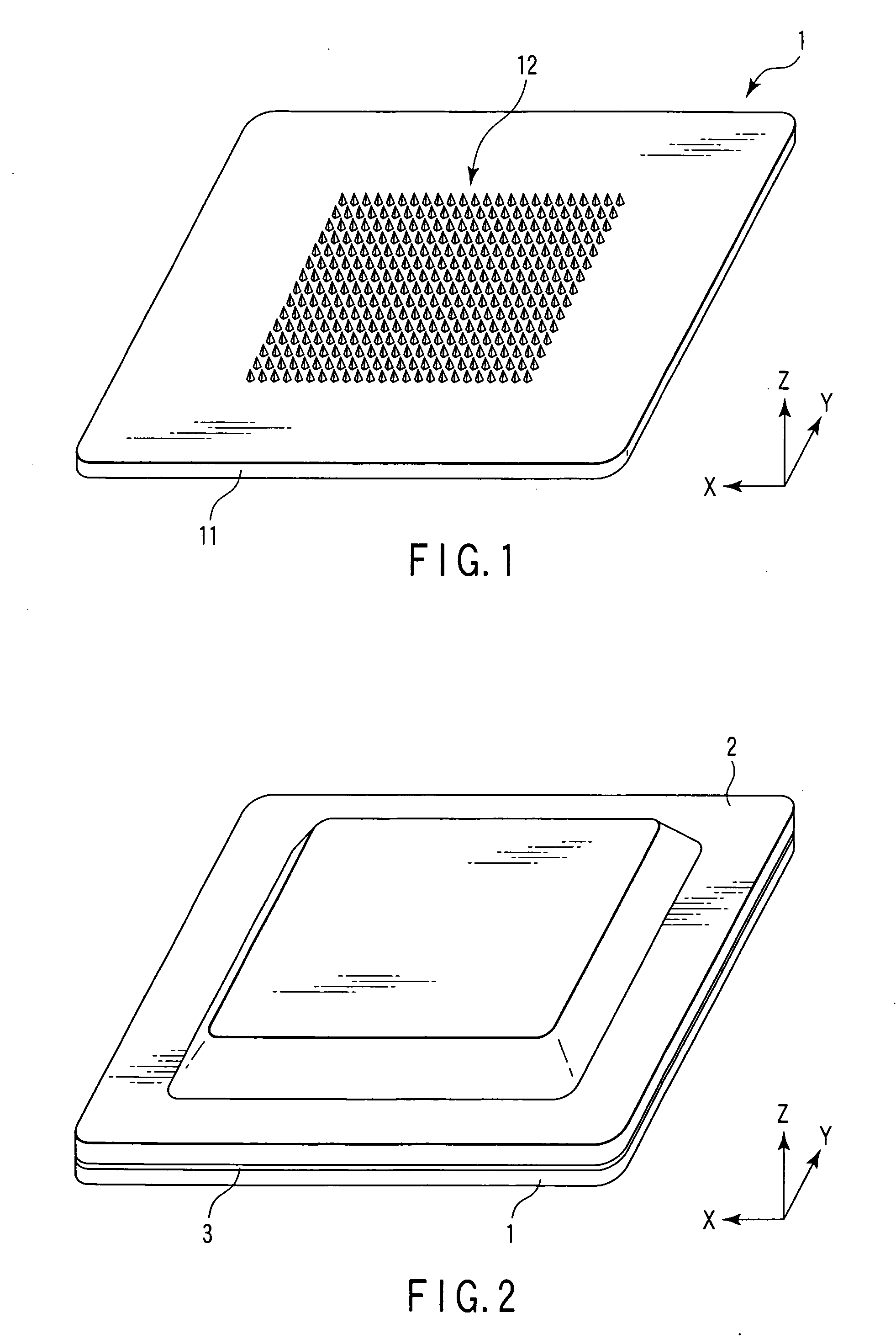
[0099]In this example, micro-needle patches 1 each having the structure shown in FIG. 1 and differing in the structures of the micro-needles 121 from one another are manufactured by the same method as described with reference to FIG. 14. To be more specific, as a material of the micro-needle patches 1, a mixture of chitin / chitosan and insulin was used. In the mixture, the sum of the chitin content and the chitosan content was set at 70% by mass, while...
example 2
[0106]FIGS. 22 and 23 are sectional views schematically showing structures of micro-needles employed in Example 2. Each of the micro-needles 121 shown in FIGS. 22 and 23 has a shape tapering down from one end to another end, and all the cross sections thereof perpendicular to the Z direction are circular. Each of the micro-needles 121 is provided with a through-hole extending in the Z direction. The micro-needle 121 shown in FIG. 21 has a symmetry axis parallel with the Z direction. On the other hand, the micro-needle 121 shown in FIG. 22 does not have a symmetry axis parallel with the Z direction.
[0107]In this example, micro-needle patches made of a mixture of chitin / chitosan and insulin were manufactured by the same method as in Example 1 except that the structures shown in FIGS. 21 and 22 were employed in micro-needles. Then, the same test as described in Example 1 were performed on the micro-needle patches. As a result, in the case where the structure shown in FIG. 21 was employ...
example 3
[0108]In this example, micro-needle patches differing in insulin contents from one another were manufactured by the same method as in Example 1. Then, the strengths of the micro-needles were determined on each of the micro-needle patches by the same method as described in Example 1. The results are shown in FIG. 23.
[0109]FIG. 23 is a graph showing the relationship between the insulin content and the strength of a micro-needle. In the figure, the abscissa denotes the insulin content, while the ordinate denotes the strength of the micro-needles.
[0110]As shown in FIG. 23, in the case where chitin / chitosan was used and the insulin content was about 50% or less, the strength of 135% or more was achieved. Also, it was seen that in this case, significantly high performances were achieved as compared with the case where maltose was used and the synergistic effect was produced.
[0111]Then, the same tests were performed using ketamine as an anesthetic instead of insulin. As a result, in the ca...
PUM
 Abstract
Description
Claims
Application Information
 - R&D
- Intellectual Property
- Life Sciences
- Materials
- Tech Scout
- Unparalleled Data Quality
- Higher Quality Content
- 60% Fewer Hallucinations
Browse by: Latest US Patents, China's latest patents, Technical Efficacy Thesaurus, Application Domain, Technology Topic, Popular Technical Reports.
© 2025 PatSnap. All rights reserved.Legal|Privacy policy|Modern Slavery Act Transparency Statement|Sitemap|About US| Contact US: help@patsnap.com


