
Capsulu type medical device

a medical device and capsule technology, applied in the field of capsule medical devices, can solve the problems of difficult deployment of the device inside the living body, unfavorable patient's comfort, and the inability to maintain the stability of the propelling device of the capsule medical device, so as to achieve accurate prevention of short circuit between flexible wires, flexibility and elasticity

Active Publication Date: 2007-07-12
OLYMPUS CORP
View PDF4 Cites 181 Cited by
  • Summary
  • Abstract
  • Description
  • Claims
  • Application Information

AI Technical Summary

Benefits of technology

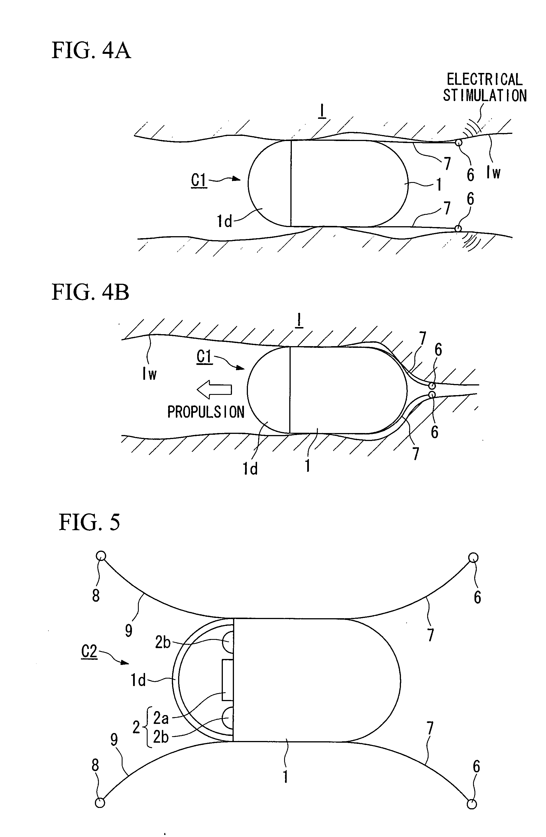
[0008] According to the capsule type medical device of the present invention, since the capsule type medical device has an interelectrode distance variation device, the electrodes are accurately made to contact body tissue and give electric stimulation. Hence, contraction movement of the body tissue is accurately achieved, which enables stable propelling of the capsule type medical device.
[0044] According to the capsule type medical device of the present invention, if the electrodes are made of a material that does not substantially expand or contract like metals and the like, mutual difference in contraction and expansion rate between the electrodes and the elastic expansion unit may be made small by mounting the electrode in the hard unit. Hence, the electrode may be mounted and maintained in the elastic expansion unit under better conditions.

Problems solved by technology

However, in this device, it is necessary to expand the balloon by blowing a fluid such as air into the capsule type medical device from outside of the living body using a tube or the like.
Hence, a relatively large tube is needed to blow the fluid into the balloon, making it difficult to deploy the device inside the living body.
Moreover, often the person examined feels uneasy or uncomfortable.
Furthermore, if the tube gets caught inside the luminal organ, stable propelling of the capsule medical device may be interrupted.
In addition, even when the flap is opened to the maximum size, the distance between the electrodes is about the same as the diameter of the capsule, hence, a problem occurs in that the device clearly cannot be used for luminal organs with a diameter larger than that of the capsule.

Method used


Image

  • Capsulu type medical device
  • Capsulu type medical device
  • Capsulu type medical device

Examples


first embodiment

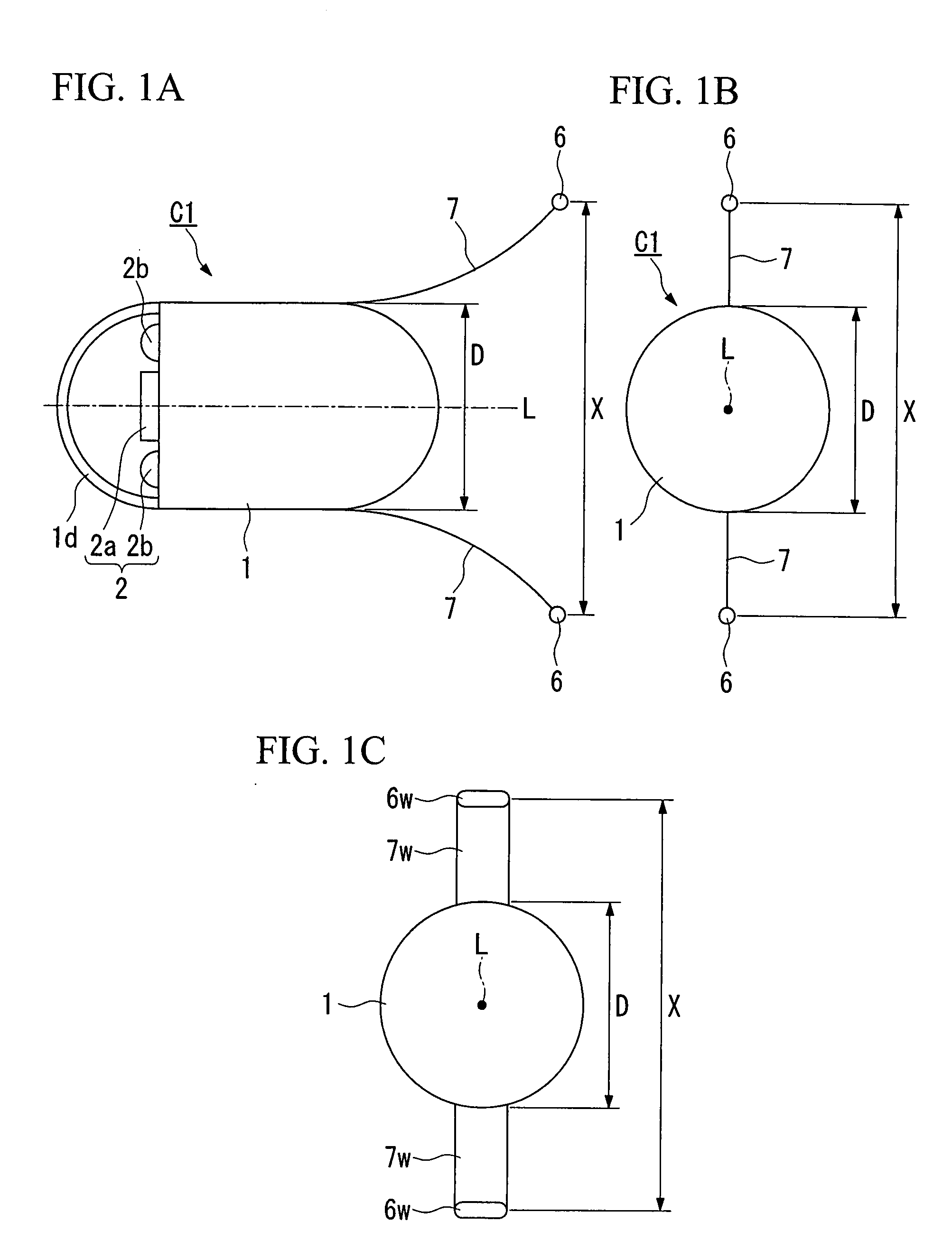
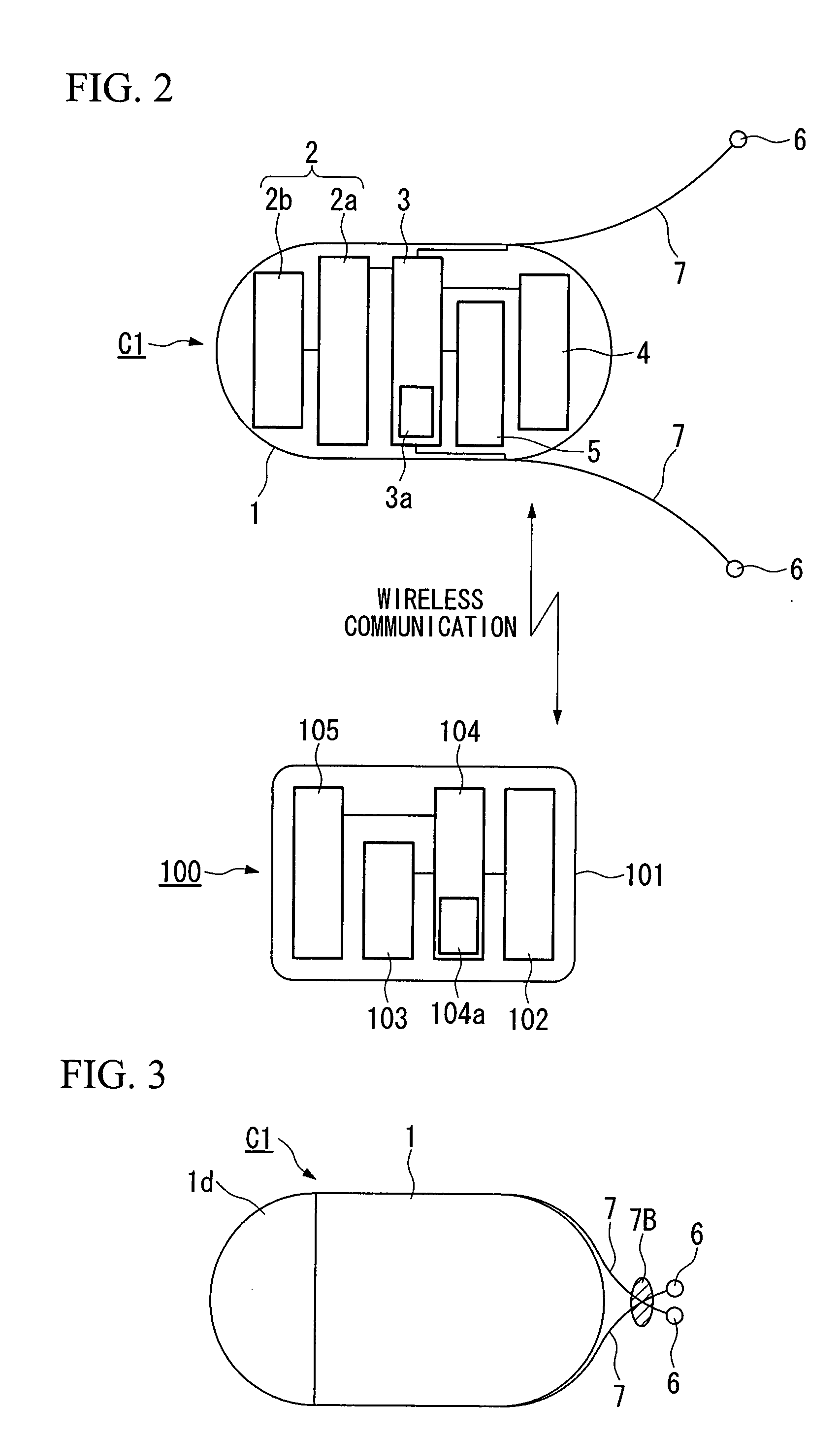
[0113] the present invention is shown with reference to FIG. 1A through FIG. 15. The capsule type medical device C1 shown in FIG. 1A through FIG. 2 is a basic configuration of a capsule type medical device in the present embodiment. This capsule type medical device C1 comprises a photography unit (in-vivo information acquisition device) 2, control unit (current control device) 3, radio transceiver unit (communication device) 4, and battery 5 for supplying power to each structural unit as one body inside a casing 1. Moreover, the capsule type medical device C1 comprises a pair of electrodes 6 and flexible wires 7. Flexible wires 7 play a role of interelectrode distance variation device that changes a distance between the pair of electrodes 6.

[0114] The casing 1 has a capsule shape extending along axis L, and is formed to seal the inside using plastic and the like. A semi-sphere shaped transparent dome 1d is provided in the front section of the casing 1. A photographing element 2a and...

second embodiment

[0202] Hereafter, deformed examples of the capsule type medical device C10 in the aforementioned second embodiment will be shown. Here, each structural element such as the photographing unit 2 (photo element 2a and light emitting element 2b), control unit 3, radio transceiver unit 4 and battery 5 of the capsule type medical device C10 is a common structural element provided in a similar manner in each of the deformed examples of the capsule type medical device below. Hence, in the following examples, presentation and detailed description of these structural elements are omitted. Moreover, other structural elements similar to those in the capsule type medical device C10 are denoted with the same symbols and detailed description of those is omitted.

[0203]FIG. 23A and FIG. 23B show a first deformed example. In the capsule type medical device C11, one pair of electrodes is anchored directly on the casing, and a weight is provided on the side where the electrode is anchored inside the ca...

third embodiment

[0220] the present invention will be shown with reference to FIGS. 26 through 40.

[0221] In this embodiment, an elastic expansion device forms the interelectrode distance variation device. The capsule-type medical device C14 shown in FIG. 26 is the basic configuration of the capsule-type medical device of the present embodiment. This capsule-type medical device C14 is provided with a capsule body (device body or casing) 201, a balloon (elastic expansion part) 202, at least one pair of bipolar electrodes 203, wires 204, a battery (power source) 5, and an expansion and contraction mechanism unit (expansion device) 16. The balloon 202 is mounted on at least one part of the capsule main body 201 and is capable of expanding elastically. The electrodes 203 are mounted on the balloon 202, and provide an electric stimulus to contractible tissue (body tissue) in the living body cavity.

[0222] The capsule main body 201 is provided, inside a casing 211, with a photographing unit (living in-vivo...


PUM


Abstract

A capsule type medical device is of a type of a capsule type medical device that is introduced inside the living body to gather in-vivo information, and comprises a capsule shaped casing; an in-vivo information acquisition device for acquiring the in-vivo information; a communication device for sending the in-vivo information acquired by the in-vivo information acquisition device to outside of the living body by wireless; at least one pair of first electrodes provided in a vicinity of one end along an axis of the casing for giving electric stimulation to body tissue in the living body; a first current control device for sending current to the first electrodes; and an interelectrode distance variation device for changing a distance between the electrodes.

Description

TECHNICAL FIELD [0001] The present invention relates to a capsule medical device that observes the living body, and in particular, a device that moves inside the living body by giving electric stimulation to body tissue, making it possible to observe desired positions. [0002] Priority is claimed on Japanese Patent Application No. 2004-261015, filed Sep. 8, 2004, and on Japanese Patent Application No. 2004-296178, filed Oct. 8, 2004, the contents of which are incorporated herein by reference. BACKGROUND ART OF THE INVENTION [0003] For a method of checking the health condition of a person being examined, such methods as medical check or examination by means of an endoscope are widely known. Moreover, an examination method that uses a capsule type medical device wherein an examination instrument formed in capsule shape is introduced inside the living body to conduct easy physical condition examination is known (for example, refer Japanese Unexamined Patent Application, First Publicatio...

Claims


Application Information

Patent Timeline
IPC IPC(8): A61N1/00
CPCA61B1/00156A61B1/041A61B2019/2253A61B5/6886A61B1/31A61B34/73A61B1/00A61J3/07
Inventor TAKIZAWA, HIRONOBUUCHIYAMA, AKIOKAWANO, HIRONAOYOKOI, TAKESHIHOMAN, MASATOSHI
Owner OLYMPUS CORP
Learn More