Method of Distributing Braking Within at Least One Group of Brakes of an Aircraft

a technology of aircraft brakes and brakes, applied in automatic braking sequences, navigation instruments, instruments, etc., can solve the problem of faster wear of friction elements, and achieve the effect of discharging energy levels

Active Publication Date: 2008-08-21
SAFRAN LANDING SYSTEMS
View PDF6 Cites 16 Cited by
  • Summary
  • Abstract
  • Description
  • Claims
  • Application Information

AI Technical Summary

Benefits of technology

[0010]estimating individual braking setpoints for each of the brakes of the group so that the individual braking setpoints make it possible, at least under normal operating conditions of the brakes, to implement braking that dissipates said energy level, the individual braking setpoints also being determined so as to satisfy at least one other given operating objective.
[0011]Thus, by specifying in advance the level of energy to be dissipated by the group of brakes before braking is performed, it becomes possible to satisfy some other operating criterion that takes account of the energy level to be dissipated, while still dissipating the energy level that is required of the group.
[0017]minimizing wear of the friction elements of the brakes of the group; or
[0018]minimizing wear of the tires associated with the brakes of the group.
[0020]minimizing the number of times the brakes in the group are actuated; or
[0021]minimizing the amplitude of the forces applied by the actuators.

Problems solved by technology

Nevertheless, that type of distribution presents certain drawbacks.
Thus, although the brakes suffer less wear overall, it can happen that the friction elements of one of the brakes heat up faster than in neighboring brakes and nevertheless reach a temperature range in which friction element wear is faster.

Method used


Image

  • Method of Distributing Braking Within at Least One Group of Brakes of an Aircraft
  • Method of Distributing Braking Within at Least One Group of Brakes of an Aircraft
  • Method of Distributing Braking Within at Least One Group of Brakes of an Aircraft

Examples


Embodiment Construction

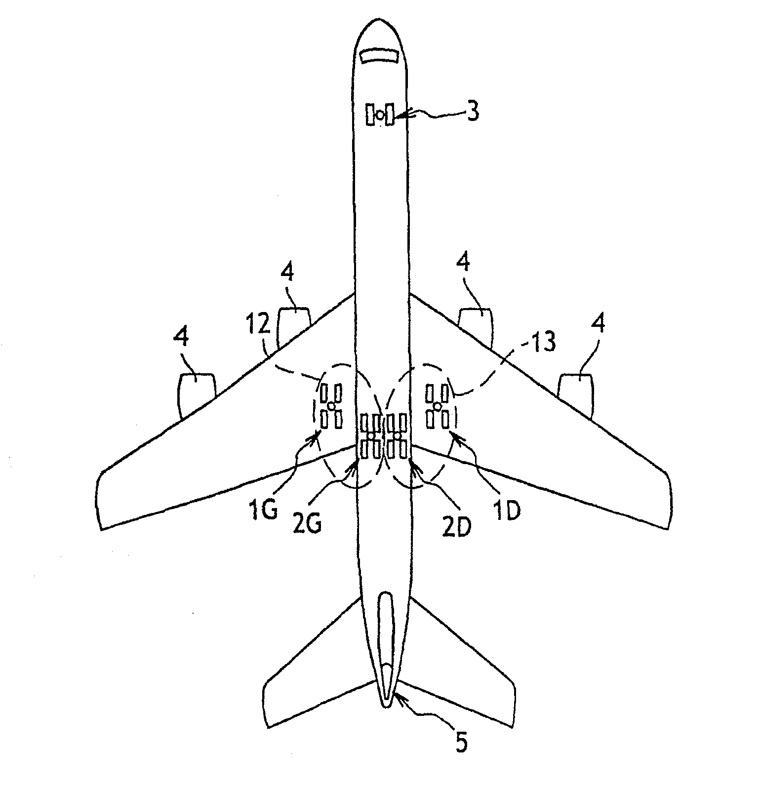
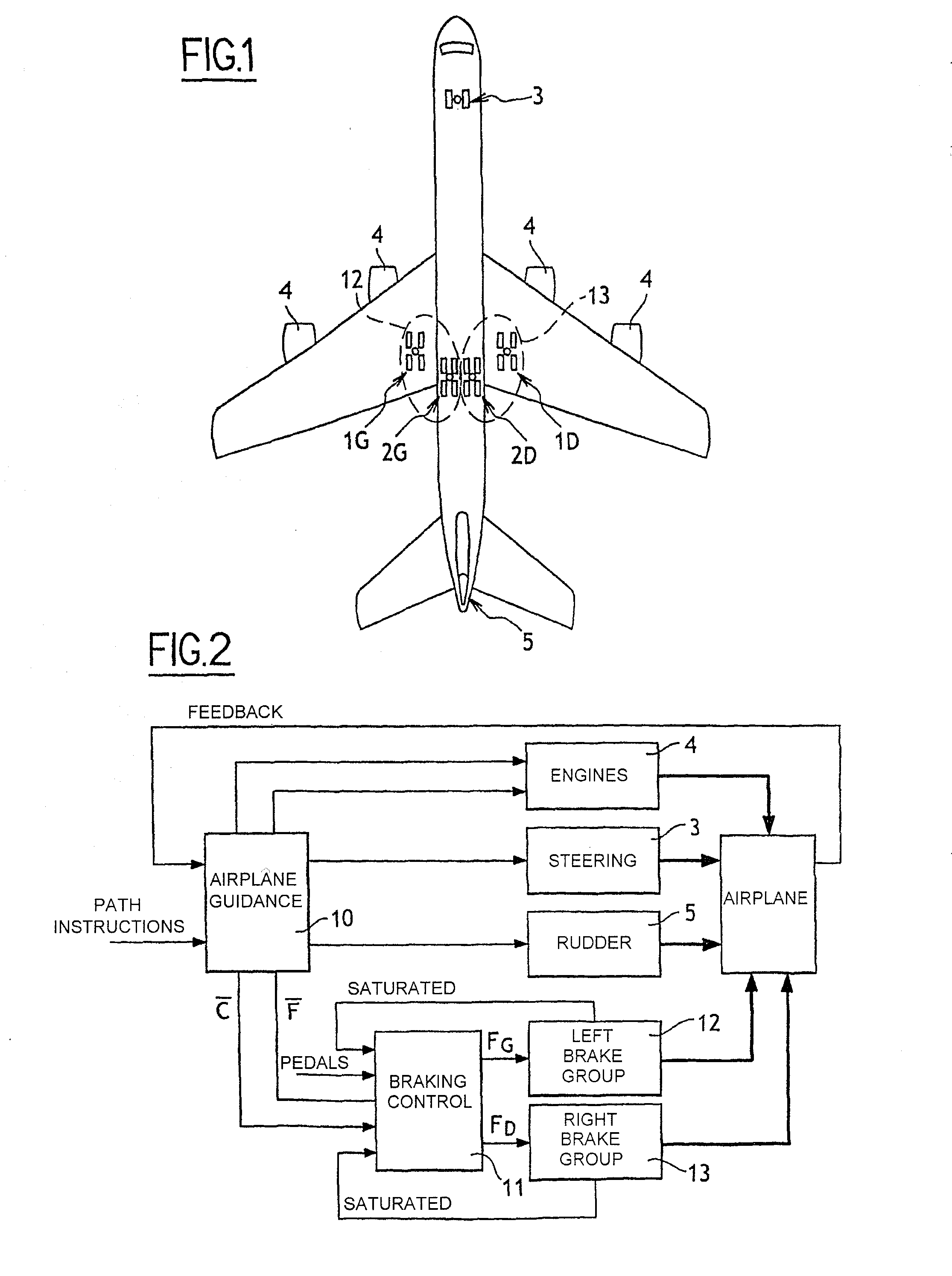
[0027]The invention is illustrated herein with reference to an aircraft of the kind shown in FIG. 1, having two main wing undercarriages 1G and 1D, two main fuselage undercarriages 2G and 2D, and a nose undercarriage 3 with steerable wheels. Each of the main undercarriages 1G, 1D, 2G, 2D has four wheels equipped with respective brakes. The aircraft is also fitted with engines 4, and with a rudder 5.

[0028]The invention applies to a ground-guidance architecture for the aircraft shown in FIG. 2 that includes an aircraft guide module 10. The guide module 10 receives as input a path setpoint (which may, where appropriate be rectilinear) and it controls all of the members that can have an influence on the path followed by the aircraft on the ground, i.e. the engines 4, the steering of the wheels of the nose undercarriage 3, the rudder 5, and naturally the brakes of the main undercarriages.

[0029]The guide module 10 generates orders for the engines 4, for the rudder 5, and for controlling t...


PUM


Abstract

The invention provides a method of managing the braking of an aircraft having a plurality of brakes comprising friction elements, the method comprising the following steps for at least one group (12, 13) of brakes:estimating an energy level (ΔE) to be dissipated by the brakes of the group; andestimating individual braking setpoints (Fi) for each of the brakes of the group so that the individual braking setpoints make it possible, at least under normal operating conditions of the brakes, to implement braking that dissipates said energy level, the individual braking setpoints also being determined so as to satisfy at least one other given operating objective.

Description

[0001]The invention relates to a method of distributing braking within at least one group of brakes of an aircraft.BACKGROUND OF THE INVENTION[0002]Aircraft of a certain size are generally fitted with a braking computer which, in order to achieve a given amount of deceleration, generates a braking force objective in response either to the pilot pressing on the brake pedals, or in response to the pilot setting a determined level of deceleration (the “autobrake” function). In practice, this braking force objective is implemented by sending braking setpoints to power driver members associated with the brakes, the setpoints being identical for all of the brakes and being such that the sum of the braking forces developed by the brakes in response thereto achieves the braking force objective. This overall braking force is applied by the braking computer for a period of time that is sufficiently long to enable the brakes to dissipate in friction the energy that is needed for achieving the ...

Claims


Application Information

Patent Timeline
Patent Type & Authority Applications(United States)
IPC IPC(8): G06F19/00
CPCB60T8/00B64C25/426B60T8/1703
Inventor DELLAC, STEPHANEJACQUET, ARNAUDGISSINGER, GERARD LEONBASSET, MICHELCHAMAILLARD, YANNGARCIA, JEAN-PIERRE
Owner SAFRAN LANDING SYSTEMS
Why Eureka
Try Eureka