Pressure augmentation "(molecular stimulation system)"

US20060174850A1Inactive Publication Date: 2006-08-10ROUTERY EDWARD EDWIN

Image

  • Pressure augmentation "(molecular stimulation system)"
  • Pressure augmentation "(molecular stimulation system)"
  • Pressure augmentation "(molecular stimulation system)"

Examples


Embodiment Construction

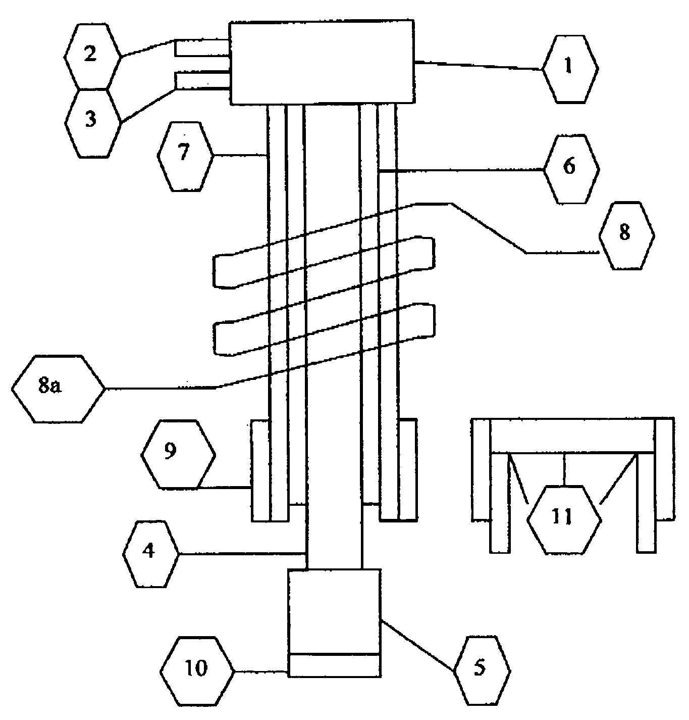
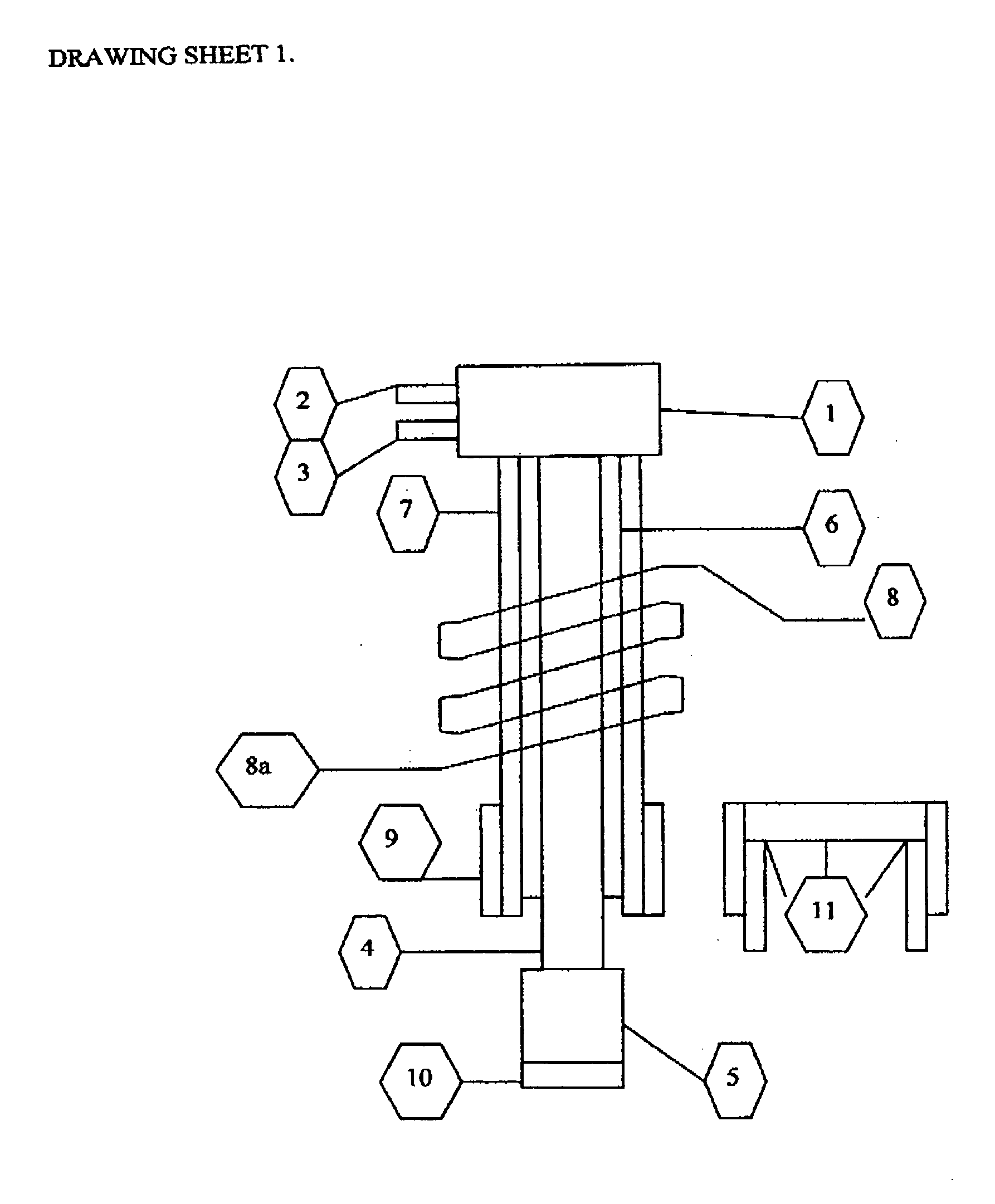
[0010] A Molecular Stimulation System according to a first embodiment includes, Circuitry for converting Direct current into a number of frequencies most suitable for molecular stimulation, including but not limited to, induction coils. Each reservoir core target provides energy, sufficient for auto-ignition of fuel in a controlled time and temperature for least pollution emissions. All reservoir core targets are energized to max sustainable energy levels of temperature for controlling combustion events. Each cylinder receives exposure to energy on demand in response to sensors and or operator input, to control temperature which controls pressure into auto-ignition of each fuel. The reservoir core target then partially recharges its energy from combustion gasses prior to total shielding, reducing the need for recharge from induction system as far as Possible, allowing lean burn, reduction of Carbon monoxide, NOx, other pollutants and improving BSFC. Each sensor varies the energy pro...


PUM


Abstract

An internal or eternal, combustion or steam driven, cylinder assembly includes a cylinder having a combustion and or expansion chamber and a piston An integrated, microprocessor and or sensor, controlled Molecular Stimulator wherein the reservoir core target receives energy on demand, at a preferred frequency and releases said energy sufficient to control temperature in combustion chamber below 2,500 degrees k when emission are a part of the design. When auto-ignition is required it can be obtained as well as best efficiency and combustion. The movement of the core targets shield exposes energy transfer to and from surface areas sufficient for auto-ignition, then allows recharge of energy from combustion event back to reservoir core target before it shuts, allowing remainder of gasses to cool for exhaust cycle.

Description

REFERENCES CITED [REFERENCED BY]U.S. Patent Documents [0001]4462345Jul. 31 1984Routery5156121Oct. 20 1992Routery5245962Sep. 21 1993Routery5724935Mar. 10 1998Routery5752481May 1998Faulkner123 / 294.5838906November 1998Doyle et al.6505601January 2003Jorach et al.6561157May 2003zur Loye et al.6637393October 2003Sutherland.2002 / 0026926March 2002Loye et al.2003 / 0097998May 2003Gray, Jr.BACKGROUND OF THE INVENTION [0002] 1. Field of the Invention [0003] The invention relates to internal combustion engines, both Otto and compression ignition. [0004] 2. Description of the Related Art [0005] With Ignition Temperatures at Various Air Pressure, ° F. (K) Air pressure, atm Gas(5)(7)(10)(15)(20)Hydrogen*1112 1100Methane*1215 1175Gasoline590480420Kerosene670490430400Gas oil580500450435Machine oil710610550520[0006] No existing systems provide the control necessary for efficient energy conversion of the above fuels. Hence the theory and technology for accomplishing same is now offered. SUMMARY OF THE ...

Claims


Application Information

Patent Timeline
10 Aug 2006
Publication
US20060174850A1
IPC
F02P23/00; F02B1/12; F02D19/10
CPC
F02D35/023; F02M27/04; F02P5/005; F02P5/145; F02P23/04
Inventors
ROUTERY, EDWARD EDWIN