

Method for fabricating exhaust gas decontamination reactor
- Summary
- Abstract
- Description
- Claims
- Application Information
AI Technical Summary
Benefits of technology
Problems solved by technology
Method used
Image

Examples
first embodiment
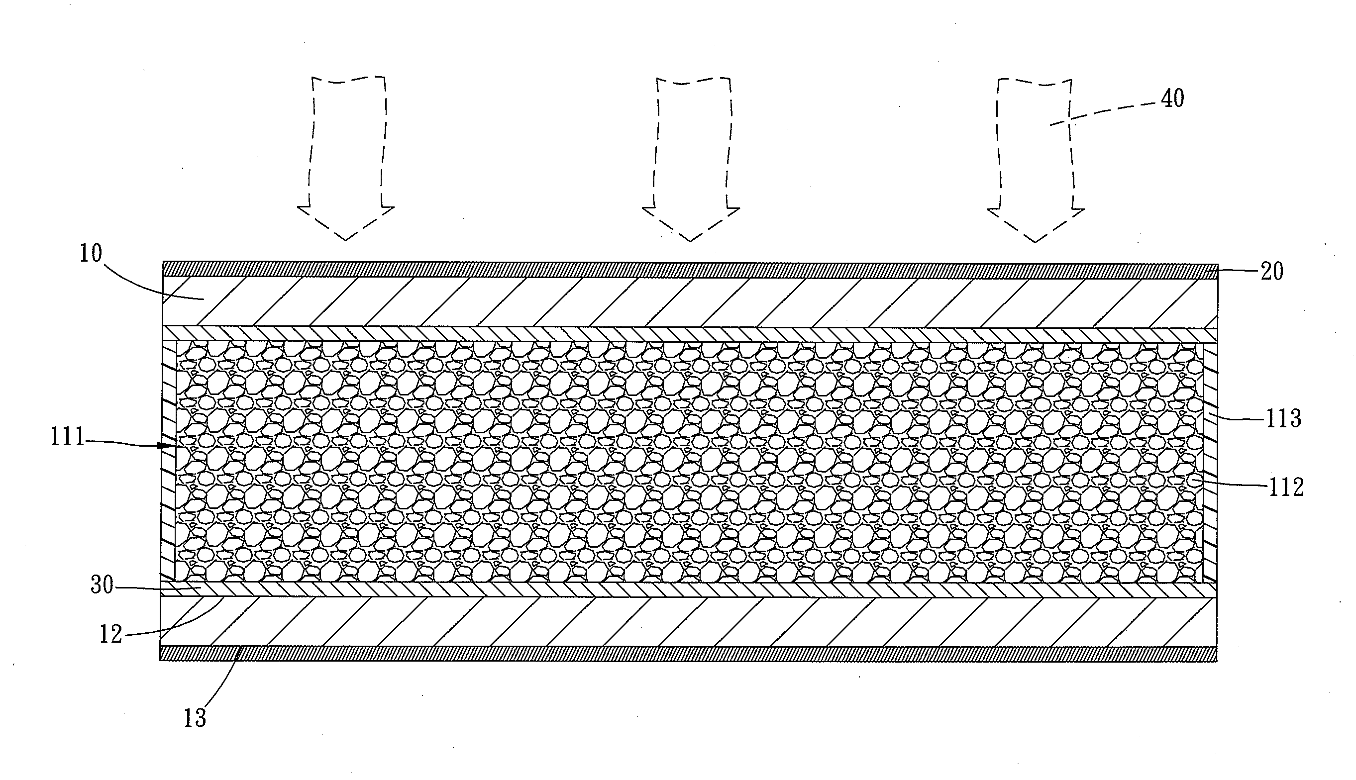
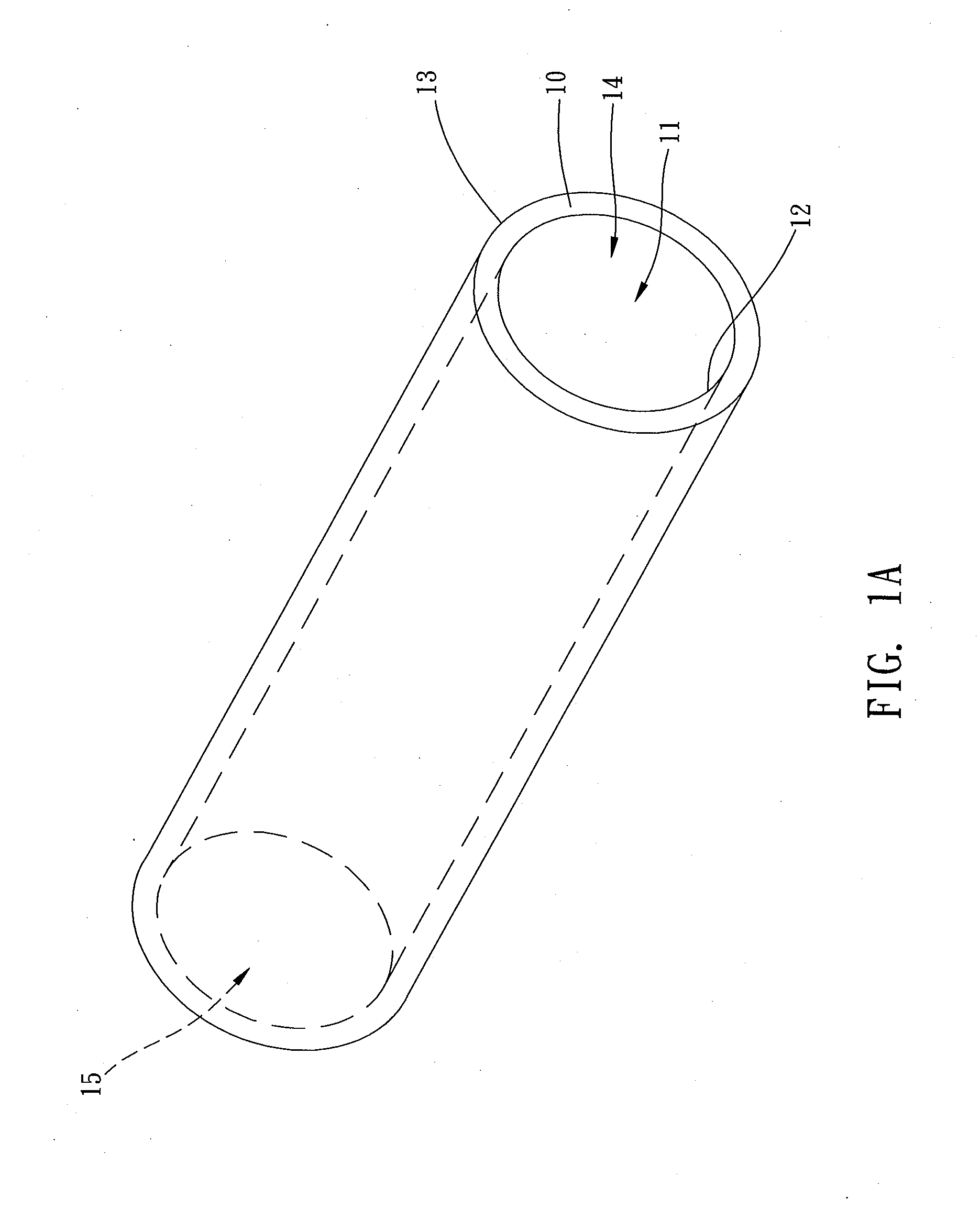
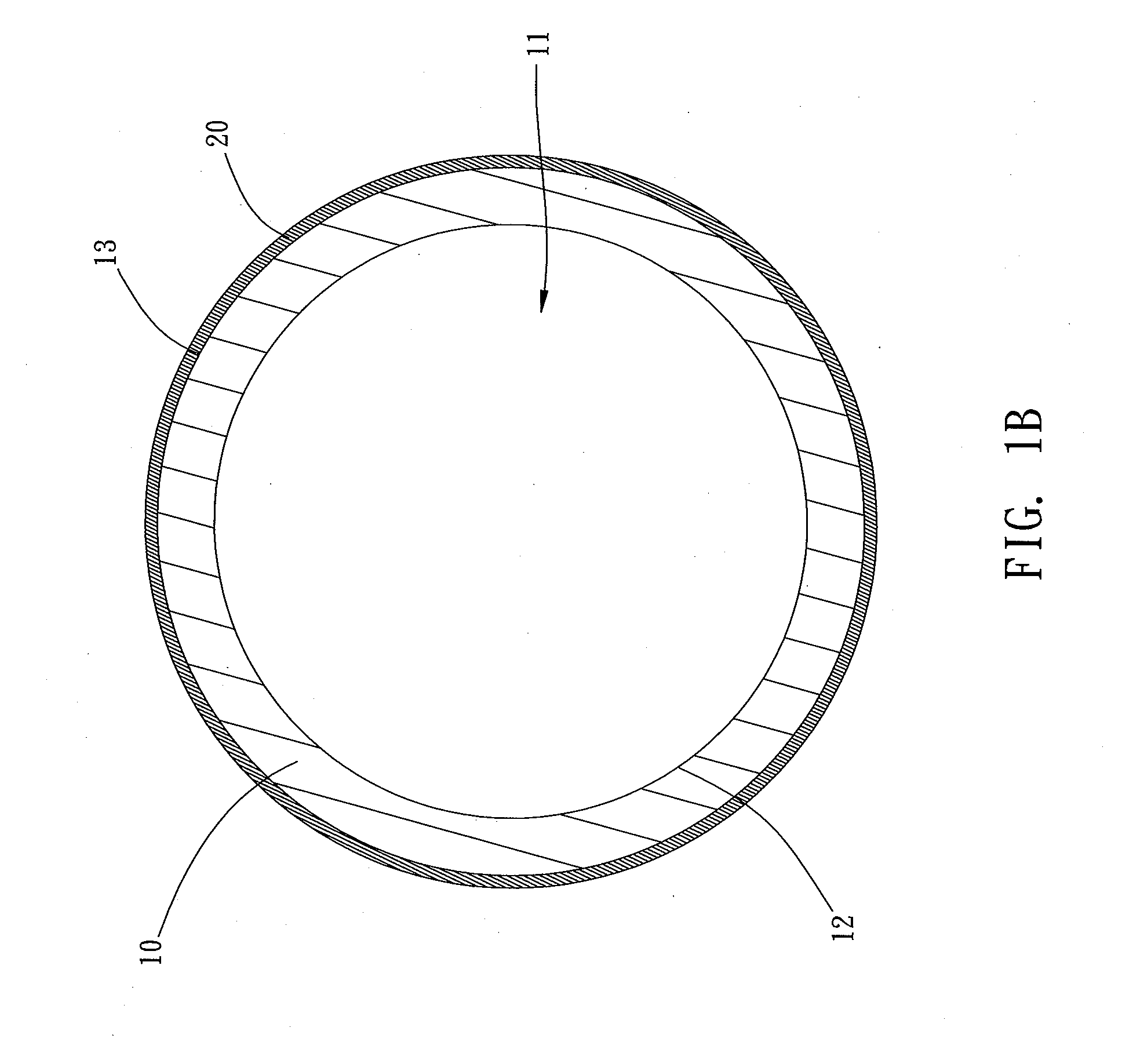
[0032]Refer to FIGS. 1A-1D diagrams schematically showing the process of fabricating an exhaust gas decontamination pipe according to the present invention. The method for fabricating an exhaust gas decontamination pipe comprises Steps 1-4.
[0033]In Step 1, provide a pipe 10 made of a solid-state oxide, as shown in FIG. 1A. The solid-state oxide is a fluoride metal oxide or a perovskite metal oxide, such as a fluorite YSZ (yttria-stabilized zirconia), a stabilized zirconia, a fluorite GDC (gadolinia-doped ceria), a dopedceria, a perovskite LSGM (strontium / magnesium-doped lanthanum gallate), or a doped lanthanum gallate. In the first embodiment, the pipe 10 is made of zirconia. The pipe 10 includes an internal channel 11, a first opening 14, a second opening 15, an inner wall surface 12, and an outer wall surface 13. The internal channel 11 is between the first opening 114 and the second opening 15 and interconnects the first opening 14 and the second opening 15. The inner wall surfac...
second embodiment
[0039]Refer to FIGS. 2A-2D diagrams schematically showing the process of fabricating an exhaust gas decontamination honeycombed structure according to the present invention. The method for fabricating an exhaust gas decontamination honeycombed structure comprises Steps A-E.
[0040]In Step A, provide a honeycombed structure 50 made of a solid-state oxide. The honeycombed structure 50 includes a plurality of tubes 51 and a plurality of separation walls 52 between each two tubes 51, as shown in FIG. 2A. The tubes 51 are separated by the separation walls 52 and arranged together. In the first embodiment, the tubes 51 have square sections. However, the present invention does not constrain that the sections of the tubes 51 must be square. In the present invention, the tubes 51 may have circular or hexagonal sections, which are closely arranged to form a compact structure.
[0041]In Step B, define in the tubes 51 a plurality of first passages 511 allowing an exhaust gas 80 (shown in FIG. 2D) t...
PUM
| Property | Measurement | Unit |
|---|---|---|
| Pressure | aaaaa | aaaaa |
Abstract
Description
Claims
Application Information