Apparatus for transferring monitor signals in photo-transfer system

Inactive Publication Date: 2005-06-21
NEC CORP
View PDF15 Cites 9 Cited by
  • Summary
  • Abstract
  • Description
  • Claims
  • Application Information

AI Technical Summary

Benefits of technology

[0057]The conventional apparatus illustrated in FIG. 1 has to include a laser module by the number equal to the number of an optical amplifier. In contrast, the present invention makes it

Problems solved by technology

The above-mentioned apparatus is accompanied with a problem that the apparatus has to include the laser module 6 by the number equal to the number of the optical amplifiers 8.
Since the laser module 6

Method used


Image

  • Apparatus for transferring monitor signals in photo-transfer system
  • Apparatus for transferring monitor signals in photo-transfer system
  • Apparatus for transferring monitor signals in photo-transfer system

Examples


Example

[First Embodiment]

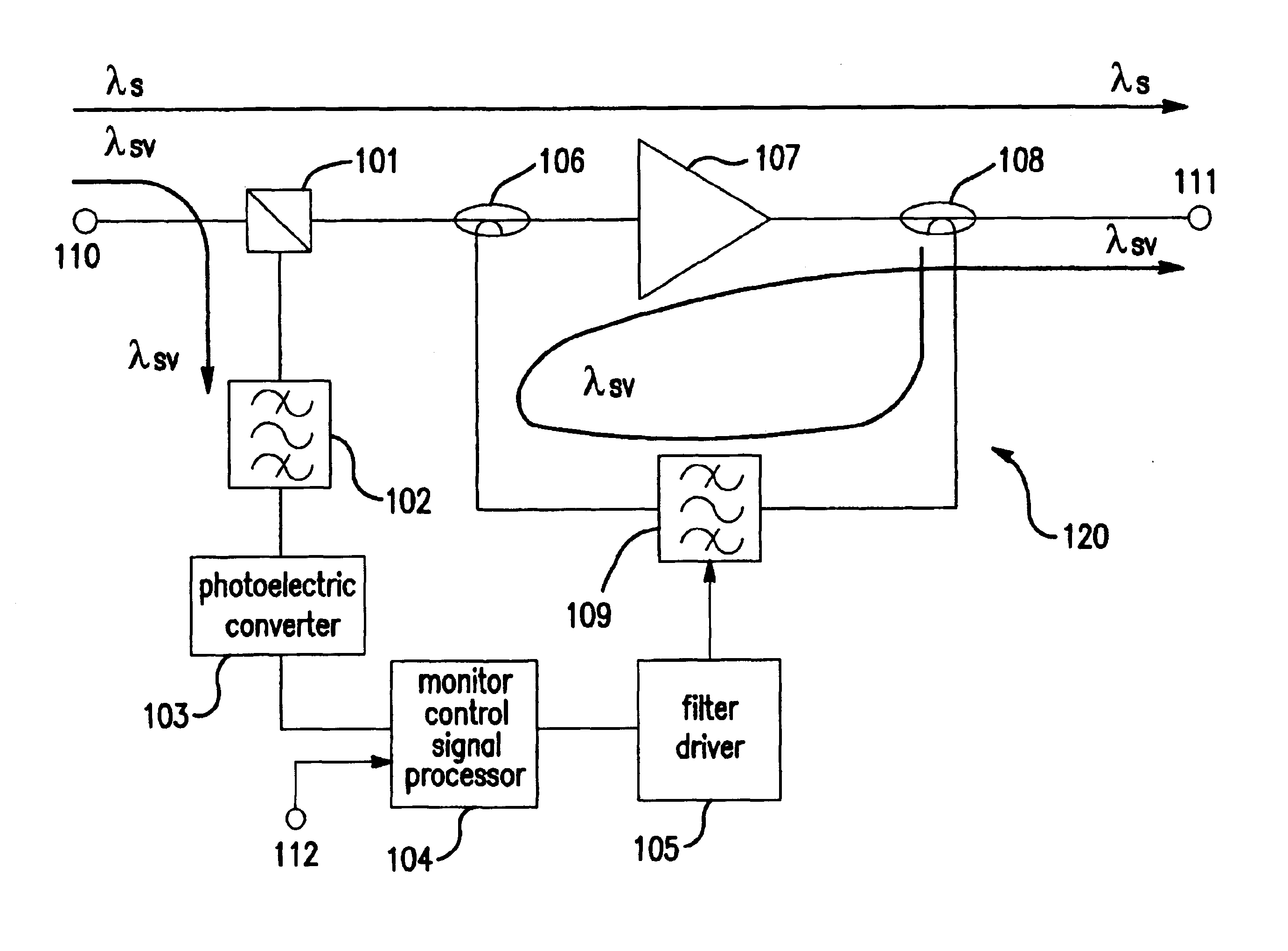
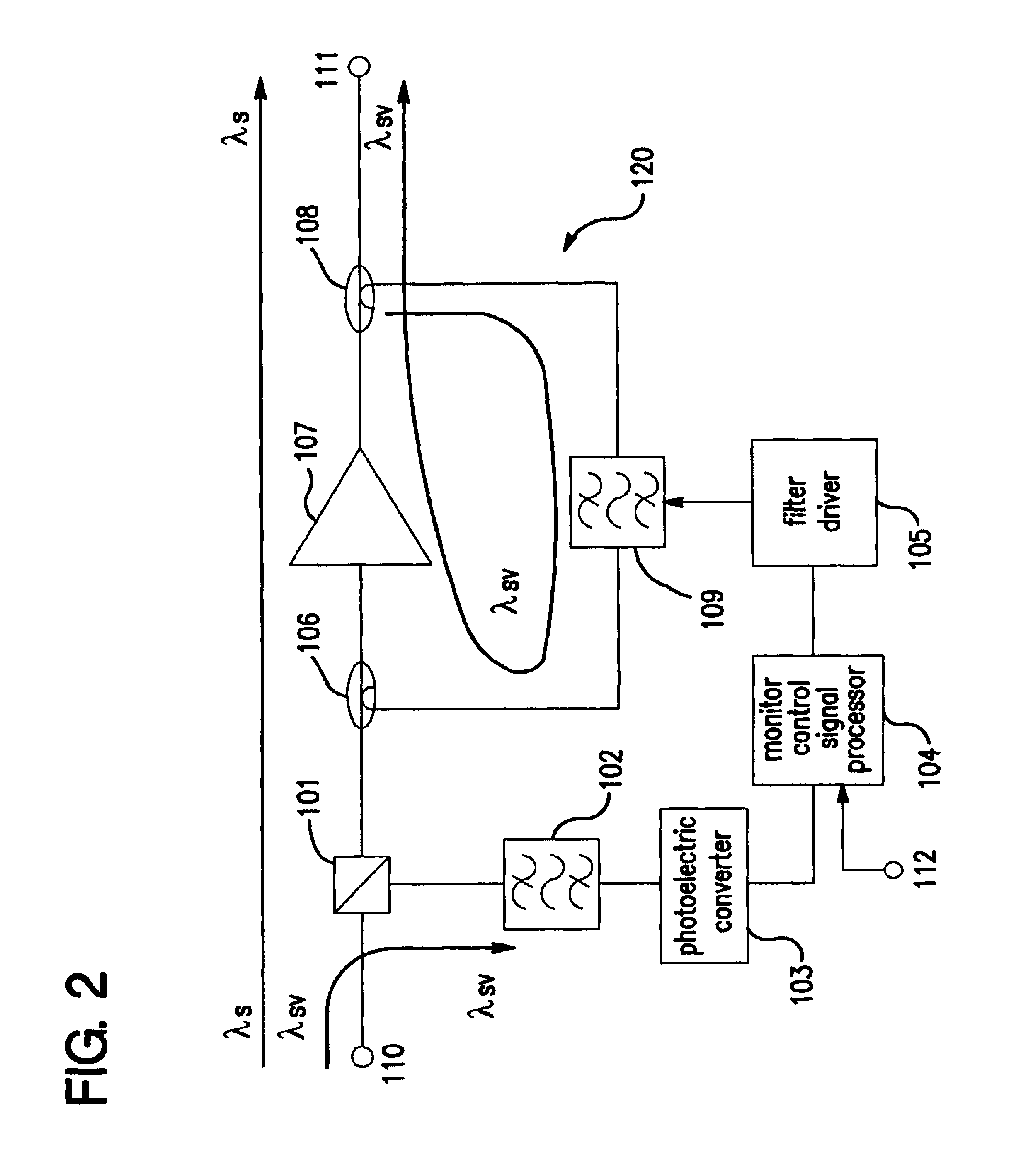
[0078]FIG. 2 is a block diagram of an apparatus of transferring a monitor signal, in accordance with the first embodiment.

[0079]The apparatus is comprised of a signal input terminal 110 receiving an optical signal comprised of a primary signal having a wavelength of λ s which signal is multiplexed with a secondary signal having a wavelength of λ sv, a wavelength division multiplex (WDM) filter 101 as a separator for separating the secondary signal from the optical multiple signal transmitted through the signal input terminal 110, a second optical band-pass filter 102 to which the secondary signal separated in the WDM filter 101 is input, a photoelectric converter 103 which converts the optical signal transmitted from the second optical band-pass filter 102, into an electric signal, a monitor control signal processor 104 which processes the electric signal transmitted from the photoelectric converter 103, together with a monitor control signal input thereinto throug...

Example

[Second Embodiment]

[0099]FIG. 6 is a block diagram of an apparatus of transferring a monitor signal, in accordance with the second embodiment.

[0100]The apparatus is comprised of a signal input terminal 211 receiving an optical signal comprised of a primary signal having a wavelength of λ s which signal is multiplexed with a secondary signal having a wavelength of λ sv, a wavelength division multiplex (WDM) filter 201 as a separator for separating the secondary signal from the optical multiple signal transmitted through the signal input terminal 211, a second optical band-pass filter 202 to which the secondary signal separated in the WDM filter 201 is input, a photoelectric converter 203 which converts the optical signal transmitted from the second optical band-pass filter 202, into an electric signal, a monitor control signal processor 204 which processes the electric signal transmitted from the photoelectric converter 203, together with a monitor control signal input thereinto thro...

Example

[Third Embodiment]

[0106]FIG. 7 is a block diagram of an apparatus of transferring a monitor signal, in accordance with the third embodiment.

[0107]The apparatus is comprised of a signal input terminal 311 receiving an optical signal comprised of a primary signal having a wavelength of λ s which signal is multiplexed with a secondary signal having a wavelength of λ sv, a wavelength division multiplex (WDM) filter 301 as a separator for separating the secondary signal from the optical multiple signal transmitted through the signal input terminal 311, a second optical band-pass filter 302 to which the secondary signal separated in the WDM filter 301 is input, a photoelectric converter 303 which converts the optical signal transmitted from the second optical band-pass filter 302, into an electric signal, a monitor control signal processor 304 which processes the electric signal transmitted from the photoelectric converter 303, together with a monitor control signal input thereinto throug...


PUM


Abstract

An apparatus for transferring monitor signals, which apparatus receives a primary signal, and a secondary signal for monitoring a wavelength, and outputs the primary signal and the modulated secondary signal. The apparatus includes an optical coupler to which the primary signal is input, a first optical branching filter optically connected to a signal output terminal, a first optical amplifier optically connected in series between the optical coupler and the first optical branching filter, and a first optical band-pass filter optically connected in series between the optical coupler and the first optical branching filter, but optically connected in parallel with the first optical amplifier. The primary signal is input into the optical coupler and output from the signal output terminal through the first optical amplifier and the first optical branching filter. The primary signal is divided into two parts by the first optical branching filter, and one of the two parts is input again into the first optical amplifier through the first optical band-pass filter and the optical coupler. The apparatus makes it possible to generate a monitor signal without employing a laser module.

Description

BACKGROUND OF THE INVENTION[0001]1. Field of the Invention[0002]The invention relates to an apparatus for transferring a monitor signal, to be used in a system for transferring an optical signal.[0003]2. Description of the Related Art[0004]FIG. 1 is a block diagram of a conventional apparatus for transferring a monitor signal, to be used in an optical-signal transferring system.[0005]The apparatus is comprised of an optical branching filter 1, an optical band-pass filter 2, a light receiver 3, a monitor control signal processor 4, a laser driver 5, a laser module 6, an optical coupler 7, and an optical amplifier 8 optically connected in series between the optical branching filter 1 and the optical coupler 7.[0006]The optical band-pass filter 2, the light receiver 3, the monitor control signal processor 4, the laser driver 5, and the laser module 6, are optically connected in series between the optical branching filter 1 and the optical coupler 7, and in parallel with the optical amp...

Claims


Application Information

Patent Timeline
IPC IPC(8): G02F1/29G02F1/335H01S3/06H04B10/02H04B10/17H01S3/10H04B10/16H04B10/08H04L25/02H04B10/07H04B10/077H04B10/29H04B10/291H04B10/54
CPCH04B10/077H04B10/0775H04B2210/078
Inventor YAMASHITA, MAKOTO
Owner NEC CORP
Why Eureka
Try Eureka