Magnetic element with multiple air gaps

Active Publication Date: 2015-10-22
DELTA ELECTRONICS INC
View PDF9 Cites 8 Cited by
  • Summary
  • Abstract
  • Description
  • Claims
  • Application Information

AI Technical Summary

Benefits of technology

[0006]The present disclosure provides a magnetic element with multiple air gaps. The coils are directly wound around the magnetic cores without the need of using bobbin. Consequently, the fabricating cost is reduced, and the coil utilization is enhanced. Since the multiple

Problems solved by technology

However, the larger air gap may

Method used


Image

  • Magnetic element with multiple air gaps
  • Magnetic element with multiple air gaps
  • Magnetic element with multiple air gaps

Examples


Example

[0015]The present disclosure will now be described more specifically with reference to the following embodiments. It is to be noted that the following descriptions of preferred embodiments of this disclosure are presented herein for purpose of illustration and description only. It is not intended to be exhaustive or to be limited to the precise form disclosed.

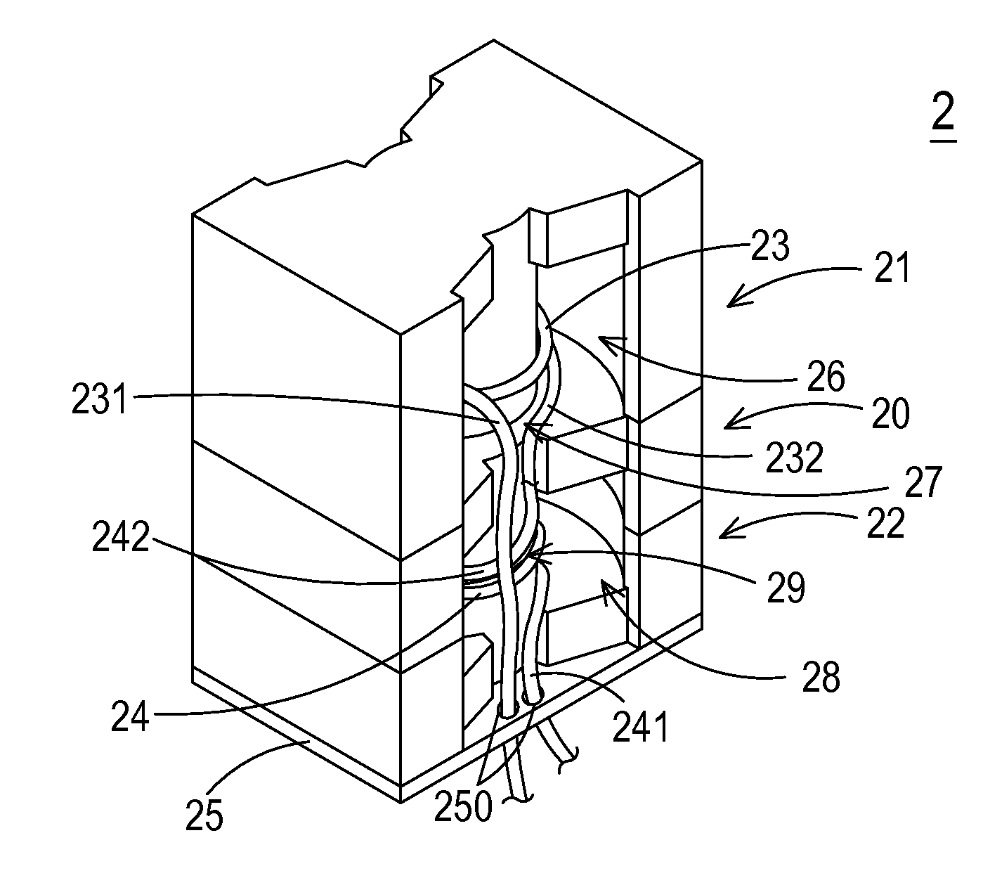
[0016]FIG. 2 is a schematic perspective view illustrating a magnetic element according to a first embodiment of the present disclosure. FIG. 3 is a schematic cross-sectional view illustrating the magnet cores of the magnetic element of FIG. 2. The magnetic element 2 of this embodiment may be applied to a power factor correction circuit or a resonant circuit of a power supply apparatus. Moreover, the magnetic element 2 is bobbinless. An example of the magnetic element 2 includes but is not limited to an inductor or a transformer. As shown in FIGS. 2 and 3, the magnetic element 2 comprises an intermediate magnetic core 20, a firs...


PUM


Abstract

A magnetic element includes a first magnetic core, a second magnetic core, an intermediate magnetic core, a first winding coil, and a second winding coil. The intermediate magnetic core is arranged between the first magnetic core and the second magnetic core. After the first magnetic core and the intermediate magnetic core are coupled with each other, a first winding space and a first air gap are defined. After the second magnetic core and the intermediate magnetic core are coupled with each other, a second winding space and a second air gap are defined. The first winding coil is disposed within the first winding space and arranged around the first air gap. The second winding coil is disposed within the second winding space and arranged around the second air gap. The first winding coil and the second winding coil are connected with each other in series.

Description

TECHNICAL FIELD[0001]The present disclosure relates to a magnetic element, and more particularly to a magnetic element with multiple air gaps.BACKGROUND OF THE DISCLOSURE[0002]Nowadays, magnetic elements such as inductors and transformers are widely used in power supply apparatuses or other electronic devices in order to generate induced magnetic fluxes.[0003]Take an inductor as an example. FIG. 1A is a schematic exploded view illustrating an inductor with an air gap. FIG. 1B is a schematic assembled view illustrating a portion of the inductor of FIG. 1A, in which the bobbin and the winding coil are not shown. The inductor 1 may be applied to a power factor correction circuit or a resonant circuit of a power supply apparatus. The conventional inductor 1 comprises a bobbin 10, a first magnetic core 11, a second magnetic core 12, and a winding coil 13. The bobbin 10 comprises a channel 101 and a winding section 102. A middle post 111 of the first magnetic core 11 and a middle post 121...

Claims


Application Information

Patent Timeline
IPC IPC(8): H01F27/24H01F27/34H01F27/30
CPCH01F27/24H01F27/346H01F27/30H01F3/14H01F17/045H01F27/306H01F27/29
Inventor LIN, HAN-HSINGLIU, CHIEN-HUNGHUNG, YU-LIANGCHEN, KUN-TECHEN, YI-LINLIU, FAN-LIN
Owner DELTA ELECTRONICS INC
Why Eureka
Try Eureka