Chemical pump and method of discharging chemical solution

Active Publication Date: 2006-05-23
SCREEN HLDG CO LTD
View PDF10 Cites 0 Cited by
  • Summary
  • Abstract
  • Description
  • Claims
  • Application Information

AI Technical Summary

Benefits of technology

[0016]Thus, the single driving element drives the partition member to reciprocate, thereby changing the volume ratio between the first chamber and the second chamber while the sum of the volumes of the first and second chambers is held constant. Therefore, the chemical pump can make the amount of change in the volume of the first chamber and the amount of change in the volume of the second chamber equal to each other precisely and simultaneously, thereby to suppress vapor lock and micro-bubble phenomena without the need to provide the acting element on the secondary side of the chemical pump.
[0017]The present invention is also intended for a method of sucking and discharging a chemical solution. The method comprises the steps of: driving in a first direction a movable partition member having opposite surfaces approximately equal in surface area within a pressure chamber divided by the partition member into a first chamber and a second chamber on opposite sides of the partition member, to increase the volume of the first chamber while decreasing the volume of the second chamber, thereby sucking and introducing the ch

Problems solved by technology

If these values are controlled to be constant, a difference in process (mainly in discharge rate distribution during a time interval between the start of the discharge to the end thereof) results in different shapes of the formed coating films from each other, to present a problem such that the repeatability of the coating films is not insured.
Thus, the coating processing unit 100 presents a problem in that the quality of the coating film thickness is dependent on t

Method used


Image

  • Chemical pump and method of discharging chemical solution
  • Chemical pump and method of discharging chemical solution
  • Chemical pump and method of discharging chemical solution

Examples


Example

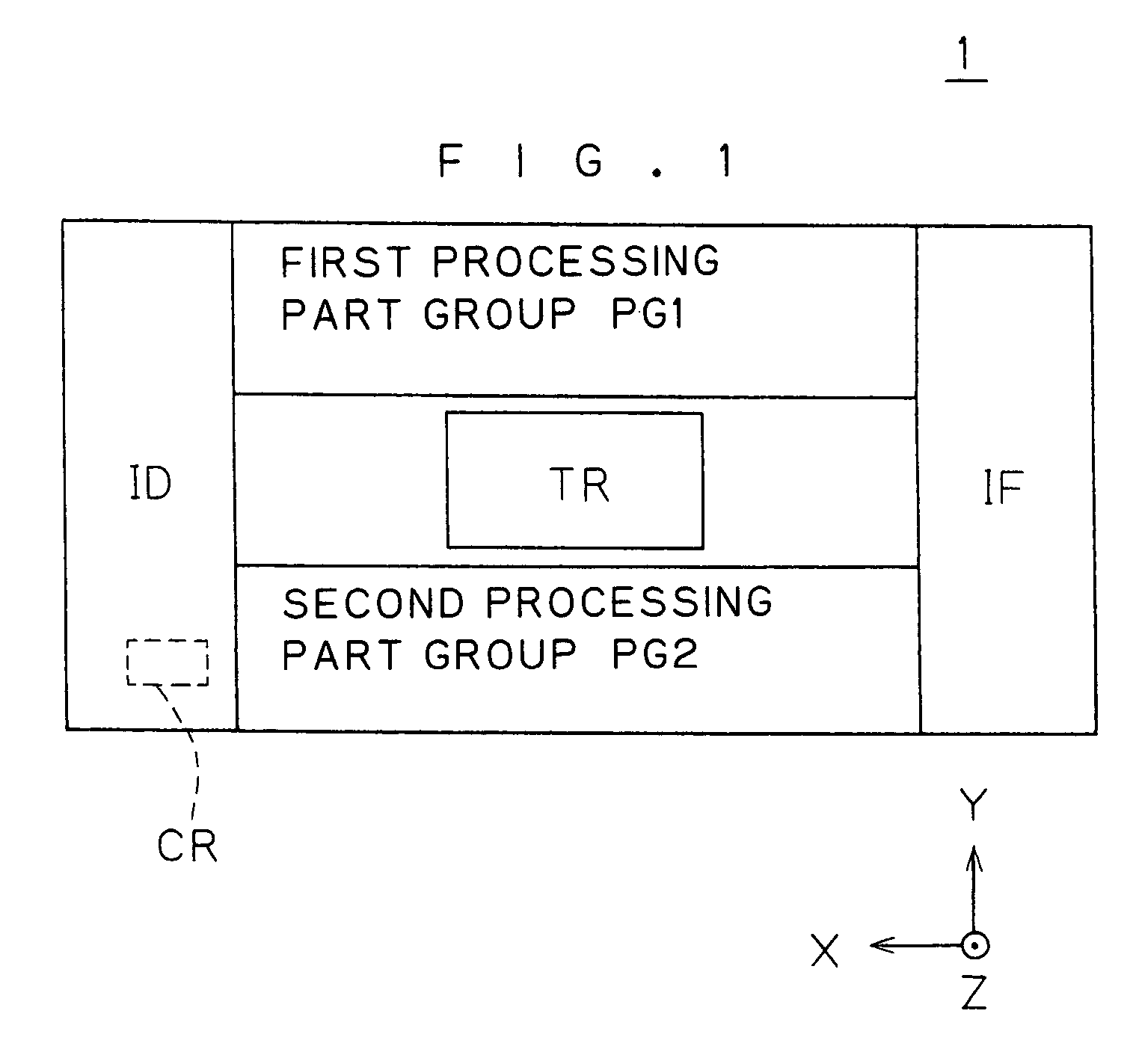
[0037]FIG. 1 is a plan view showing the overall construction of a substrate processing apparatus 1 according to a preferred embodiment of the present invention. For the sake of definiteness of directions relative to each other, an XYZ rectangular coordinate system is illustrated, as required, in FIG. 1 and its subsequent figures.

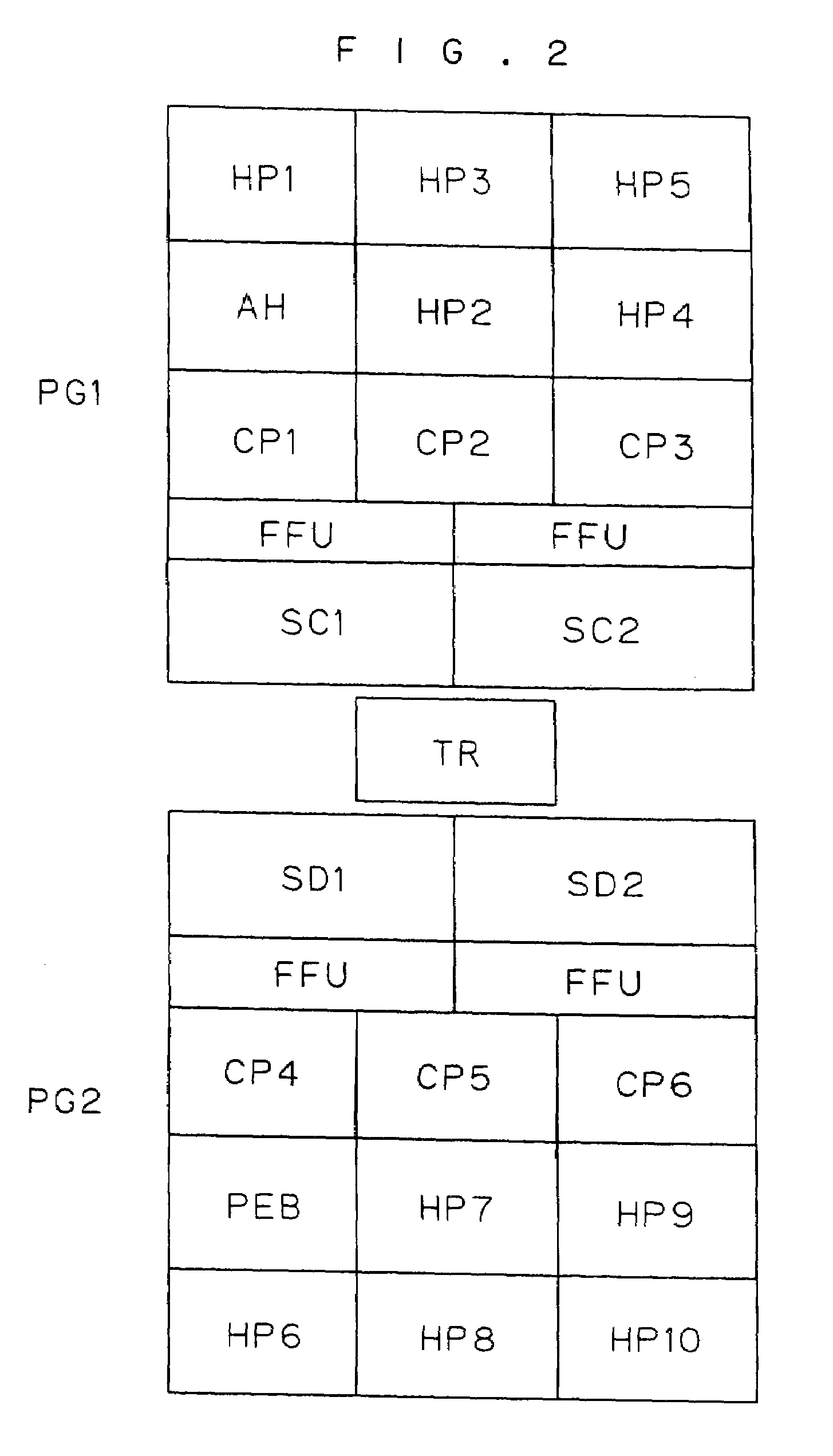
[0038]The substrate processing apparatus 1 performs a resist coating process and a development process on objective surfaces of respective substrates. The substrate processing apparatus 1 comprises: an indexer ID for transporting the substrates into and out of the substrate processing apparatus 1; a first processing part group PG1 and a second processing part group PG2 each including a plurality of processing units for performing processes on the substrates; an interface IF for transferring the substrates to and from an exposure apparatus (or a stepper) not shown; and a transport robot TR.

[0039]The substrates to be processed by the substrate processing appar...


PUM


Abstract

A chemical pump includes a pressure chamber, a partition member for dividing the pressure chamber into a cleaning pressure chamber and a discharging pressure chamber, a filter part disposed on the primary side of the discharging pressure chamber, and a single drive mechanism. A pair of openings with respective check valves mounted therein are provided in each of the cleaning and discharging pressure chambers, and are positioned so as to cause a resist solution to flow only in the +Z direction. The drive mechanism moves the partition member in the −X direction to cause the resist solution to be sucked into the cleaning pressure chamber and to cause the resist solution to be discharged from the discharging pressure chamber. The drive mechanism moves the partition member in the +X direction to cause the resist solution to be sucked from the filter part into the discharging pressure chamber and to cause the resist solution to be supplied from the cleaning pressure chamber to the filter part so that the sucked resist solution is equal in amount to the supplied resist solution. This prevents vapor lock and micro-bubble phenomena during the discharge of the resist solution.

Description

BACKGROUND OF THE INVENTION[0001]1. Field of the Invention[0002]The present invention relates to a technique for discharging a chemical solution onto an objective surface of a substrate.[0003]2. Description of the Background Art[0004]Semiconductor products, LCD products and the like are manufactured by performing on substrates a series of processes including cleaning, resist coating, exposure, development, etching, interlayer insulation film formation, heat treatment and the like. These processes are conventionally performed in a substrate processing apparatus having incorporated therein a plurality of processing units such as a coating processing unit and a heat treatment unit. A transport robot in the substrate processing apparatus transports the substrates between the plurality of processing units in a predetermined sequence, and the processing units perform respective processes on the substrates, whereby the substrate processing sequence proceeds.[0005]Of the processing units, a...

Claims


Application Information

Patent Timeline
IPC IPC(8): B05C11/08B05C11/10G03F7/16B05D1/40B05D3/00F04B3/00F04B9/02F04B13/02F04B53/06G03F7/30H01L21/00H01L21/027
CPCF04B13/02F04B53/06H01L21/6715H01L21/67017Y10T137/7838
Inventor MORITA, AKIHIKO
Owner SCREEN HLDG CO LTD
Why Eureka
Try Eureka