

Liquid ejecting apparatus and method for controlling liquid ejecting apparatus
- Summary
- Abstract
- Description
- Claims
- Application Information
AI Technical Summary
Benefits of technology
Problems solved by technology
Method used
Image

Examples
first embodiment
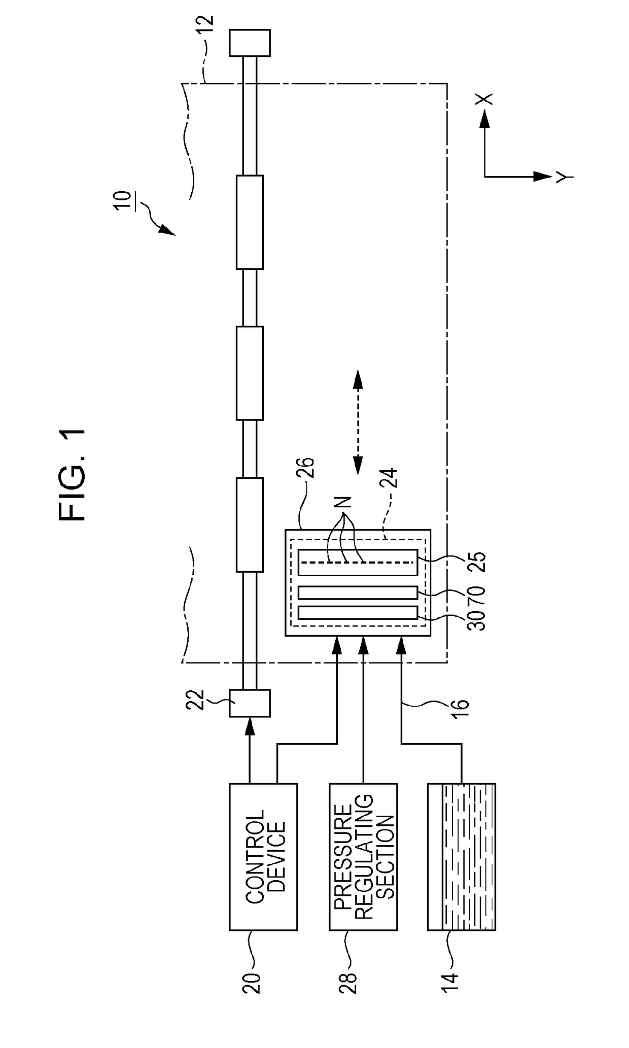
[0037]FIG. 1 is a partial structural diagram of a liquid ejecting apparatus 10 according to a first embodiment of the invention. The liquid ejecting apparatus 10 of the first embodiment is an ink jet printer that ejects ink as an example of liquid onto a medium 12 such as print paper. The liquid ejecting apparatus 10 illustrated in FIG. 1 includes a control device 20, a transport mechanism 22, a liquid ejecting unit 24, a carriage 26, and a pressure regulating section 28. A liquid container (cartridge) 14 that stores the ink is mounted on the liquid ejecting apparatus 10. The ink is supplied from the liquid container 14 to the liquid ejecting unit 24 via a liquid supplying tube 16.
[0038]The control device 20 comprehensively controls the respective elements of the liquid ejecting apparatus 10. The transport mechanism 22 transports the medium 12 in a Y direction under the control of the control device 20. The liquid ejecting unit 24 includes a filter unit 30, a valve unit 70, and a li...
first modified example
Filter Unit
[0055]FIG. 5 is a sectional view illustrating the structure of a filter unit 30 according to a first modified example. In the respective modified examples exemplified below, elements similar to those of the first embodiment in terms of operations and functions are denoted by the same reference symbols as those used in the description with reference to FIG. 2 to FIG. 4, and detailed description of those elements is omitted as appropriate.
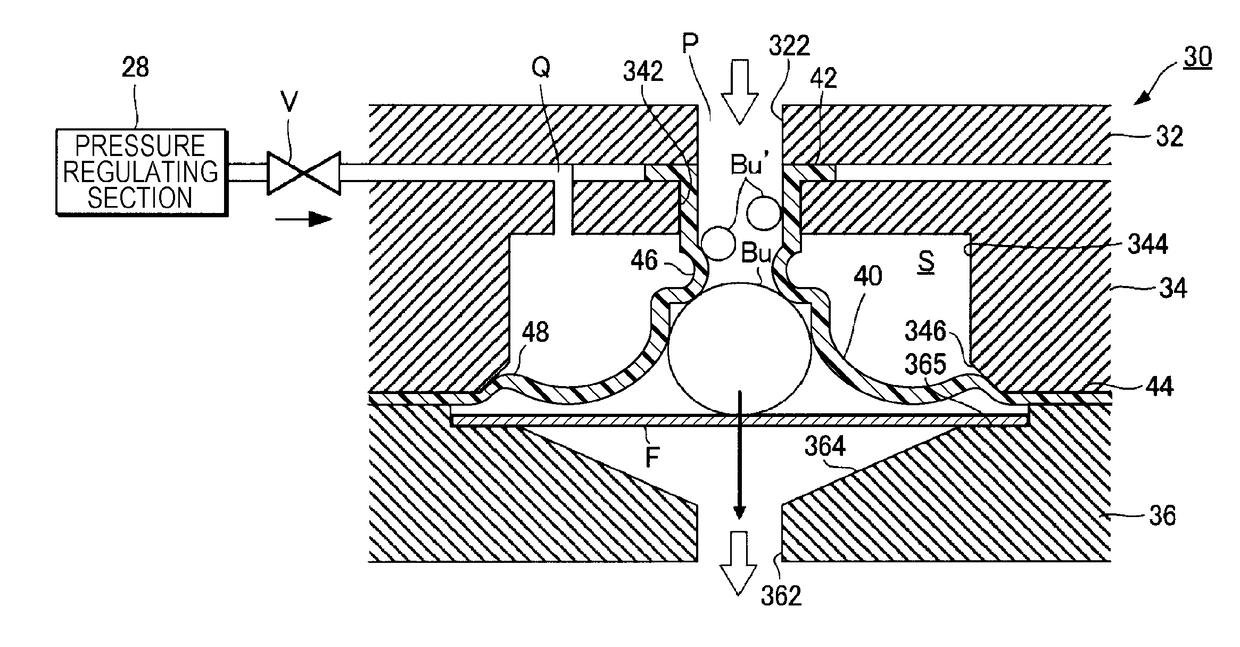
[0056]The filter unit 30 illustrated in FIG. 5 is directed to a case where, when the gas permeable film 40 is deflected inward, the thin portion 46 on the flow channel 322 side functions as a closing portion that closes the flow channel P on the flow channel 322 side of the gas permeable film 40. With this filter unit 30, when the gas permeable film 40 is deflected inward, the thin portion 46 closes the flow channel P on the flow channel 322 side of the gas permeable film 40, and then the air bubble Bu inside the flow channel P is discharg...
second modified example
Filter Unit
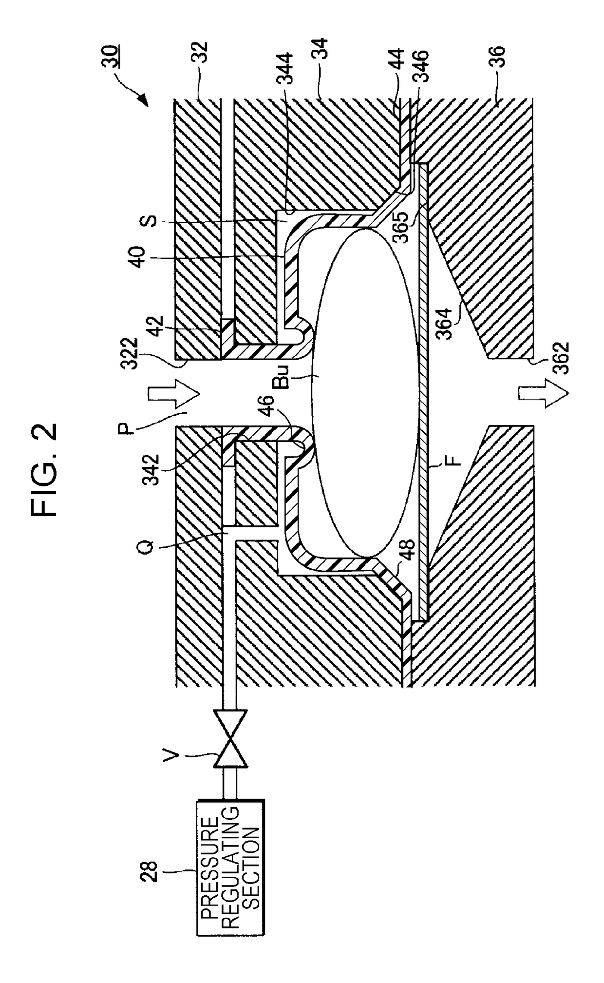
[0057]FIG. 6 is a sectional view illustrating the structure of a filter unit 30 according to a second modified example. The filter unit 30 of FIG. 6 is directed to a case where the gas permeable film 40 is formed into a bag shape and the internal space of the gas permeable film 40 is set as the air chamber S. An ink flow channel 345 that communicates with the recess 344 is formed in each of the support 32 and the air chamber forming member 34. In the filter unit 30 of FIG. 2, the internal space of the gas permeable film 40, the flow channel 322, the liquid flow port 364, and the flow channel 362 constitute the flow channel P, whereas in the filter unit 30 of FIG. 6, the external space of the gas permeable film 40 (space surrounded by the inner wall of the recess 344 and the outer wall of the gas permeable film 40), the flow channel 345, the liquid flow port 364, and the flow channel 362 constitute the flow channel P. Thus, in the filter unit 30 of FIG. 2, the inner wall o...
PUM
 Abstract
Description
Claims
Application Information