Adjustable foldable support brace

a support brace and foldable technology, applied in the direction of building parts, building material handling, construction, etc., can solve the problems of limiting the ability of adjusting the position of the optional platform ledge vertically downwardly along the main frame towards the ground relative to the support leg member, the mechanism is expensive, heavy, and burdensome to use, and achieves the effect of increasing the adjustability of the platform devi

Inactive Publication Date: 2008-08-28
TAPCO BRACE
View PDF23 Cites 27 Cited by
  • Summary
  • Abstract
  • Description
  • Claims
  • Application Information

AI Technical Summary

Benefits of technology

[0011]In accordance with its preferred form, the phasing of the adjustment points provided along first and second portions of the support leg member enables users of the device to make small adjustments in the length of the support leg member with resultant small adjustments in the vertical inclination of the main frame member even though the respective holes provided on each of the support leg members are spaced apart in a course relationship.
[0012]In accordance with a further advantage, the configuration of the lateral support strut of the platform device for supporting the transverse platform member relative to the main frame enables the support strut member to extend through the platform thus permitting the platform device to be adjusted to a point corresponding to the region of pivotal connection between the support leg member and the main frame. Essentially, the lateral support strut spans the support leg member of the main frame enabling the support leg member to extend through the lateral support brace. This allows a compactness between the platform device and the support leg member with a resultant overall increase in adjustability of the platform device relative to the main frame.

Problems solved by technology

While braces of the type described in the '254 patent have met with some success, the overall design thereof limits the ability of adjusting the location of the optional platform ledge vertically downwardly along the main frame towards the ground and relative to the support leg member.
More particularly, the structure of the optional ledge creates an interference which does not permit overlapping of the support leg member and the swinging platform support portion of the optional platform ledge.
Therefore, the platform cannot be moved to a position along the main frame vertically downwardly beyond the point on the main frame where the lower end of the swinging ledge support brace interferes with the upper end of the support leg member.
This mechanism is expensive, heavy, and burdensome to use, particularly with regard to adjustment because the interface between the threaded fastener and threaded screw can become clogged with concrete, dirt, and other debris making adjustment of the support leg member difficult or impossible.

Method used


Image

  • Adjustable foldable support brace
  • Adjustable foldable support brace
  • Adjustable foldable support brace

Examples


Embodiment Construction

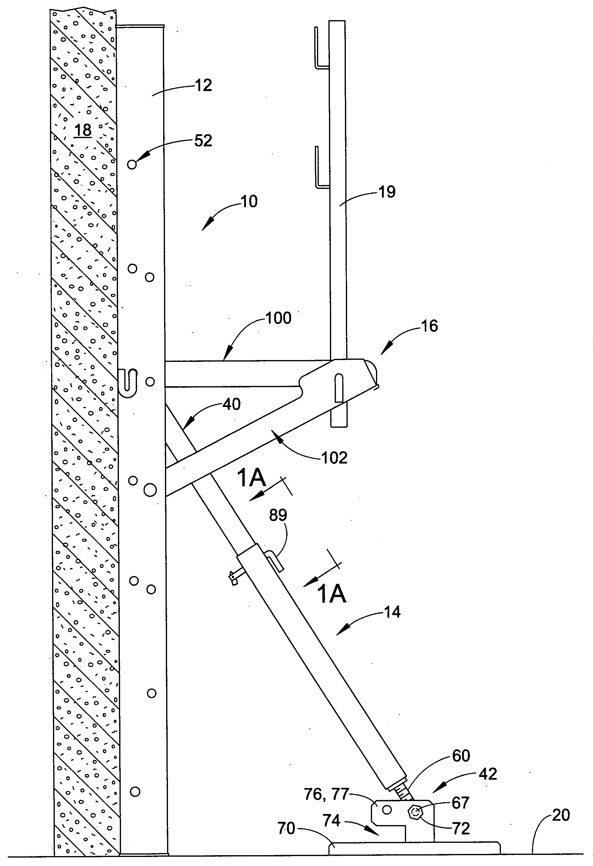
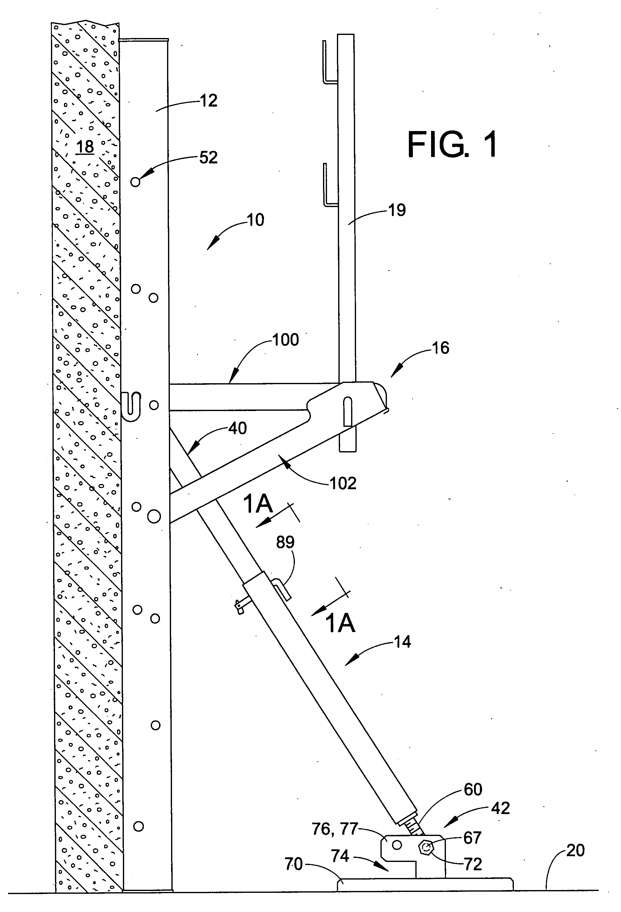
[0025]Referring now to the drawings, wherein the showings are for purposes of illustrating the preferred embodiments only and not for purposes of limiting same, FIG. 1 shows a side view of a portable support brace 10 formed in accordance with a first preferred embodiment. The brace is illustrated as arranged during use thereof in an unfolded or opened condition. In general, the support brace 10 includes a main frame 12, a support leg member 14, and a platform device 16. In general, portable support braces of the type described herein are well suited for use in supporting newly constructed and vertically disposed cast in place concrete and other walls such as insulated concrete form (ICF) block walls 18 relative to an associated stable or ground surface 20. Typical associated walls 18 include Styrofoam forms filled with concrete or other pourable materials for setting up within the Styrofoam forms. In practice, the support braces 10 are used to maintain the walls 18 in a true vertica...


PUM


Abstract

A resusable, foldable, and portable support brace includes a main frame, a support leg member, and a length adjusting device for adjusting a length of the support leg member. The main frame has a rear channel portion and a front vertical frame portion configured to engage and support an associated vertically disposed ICF block wall or other wall types relative to a ground surface. The length adjusting device adjusts a length of the leg support member between first and second ends thereof, the length adjusting device including a plurality of first and second length adjustment selection points spaced apart by respective first and second distances wherein the first and second distances are unequal. In another form, the support brace includes a platform device connected with the main frame and including a transverse arm member and a lateral strut member which spans the support leg member so that the platform device can be disposed along the main frame at a height corresponding to the upper end of the support leg member.

Description

BACKGROUND[0001]The present application is directed to the art of equipment used in construction for bracing structures such as walls and, in particular, to reusable, foldable, and portable support braces for use in supporting newly constructed vertically disposed cast in place concrete walls. Devices of the type described are especially useful in bracing newly constructed vertically disposed insulated concrete form (ICF) block walls relative to a ground surface adjacent the walls and will be described in connection thereto. However, it is to be appreciated that the embodiments of the present application have other uses and purposes, and realize advantages in other applications beyond those found in the construction arts. As an example, the embodiments are useful for bracing equipment or workpieces in industry, and for supporting temporary or movable walls such as in theatre or for business or commercial purposes and in any other applications where there is a need for providing supp...

Claims


Application Information

Patent Timeline
Patent Type & Authority Applications(United States)
IPC IPC(8): E04G21/26
CPCE04G21/26E04G17/002
Inventor MARSHALL, CHESTER R.MCCUE, JAMES D.
Owner TAPCO BRACE
Why Eureka
Try Eureka