
Dynamic gas blending

a gas blending and dynamic technology, applied in water supply installations, process and machine control, instruments, etc., can solve the problems of toxic products, hazardous process gases utilized in the semiconductor industry, and undesirable off-spec product gas concentrations, etc., and achieve the effect of small adjustments

Inactive Publication Date: 2012-09-13
PRAXAIR TECH INC
View PDF8 Cites 12 Cited by
  • Summary
  • Abstract
  • Description
  • Claims
  • Application Information

AI Technical Summary

Benefits of technology

[0008]The present invention utilizes a protocol for dynamically gas blending a combination of the balance gas, active gas, and recycled off-spec gas. This technique has the effect of enabling relatively small adjustments to the concentration of the off-spec product gas, as compared to the related art, by regulating flow rates of the balance gas and active gas to be re-blended with a recycled stream of the off-spec gas to achieve a target concentration.

Problems solved by technology

Many of the process gases utilized within the semiconductor industry are hazardous.
The off-spec product gas has an off-spec concentration that is undesirable because the off-spec product gas cannot be subsequently used downstream in processes, such as, for example, chemical vapor deposition, atomic layer deposition, or physical vapor deposition.
As a result, the off-spec product gas can lead to toxic products, increased waste gas and increased operational costs.
Furthermore, because the off-spec product gas consists of gaseous mixtures that are typically hazardous to humans and the environment, appropriate abatement systems for disposal of the waste gases must be utilized.
This undesirably increases material and operational costs, while decreasing the utilization of the active and balance gases.
As previously mentioned, even a slight deviation from the target concentration may lead to off-spec product gas.
However, to this end, the production flow control devices responsible for regulating the flow of the active and balance gases typically may not have the accuracy and precision to regulate at the much lower required flow rate.
As a result, the production flow control devices may be unable to regulate such a relatively small amount of gas flow to adjust the off-spec concentrations of the off-spec product gas mixtures into an acceptable concentration range suitable for downstream processing.

Method used


Image

  • Dynamic gas blending
  • Dynamic gas blending
  • Dynamic gas blending

Examples


Embodiment Construction

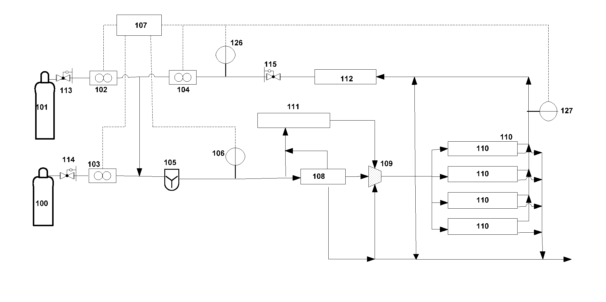
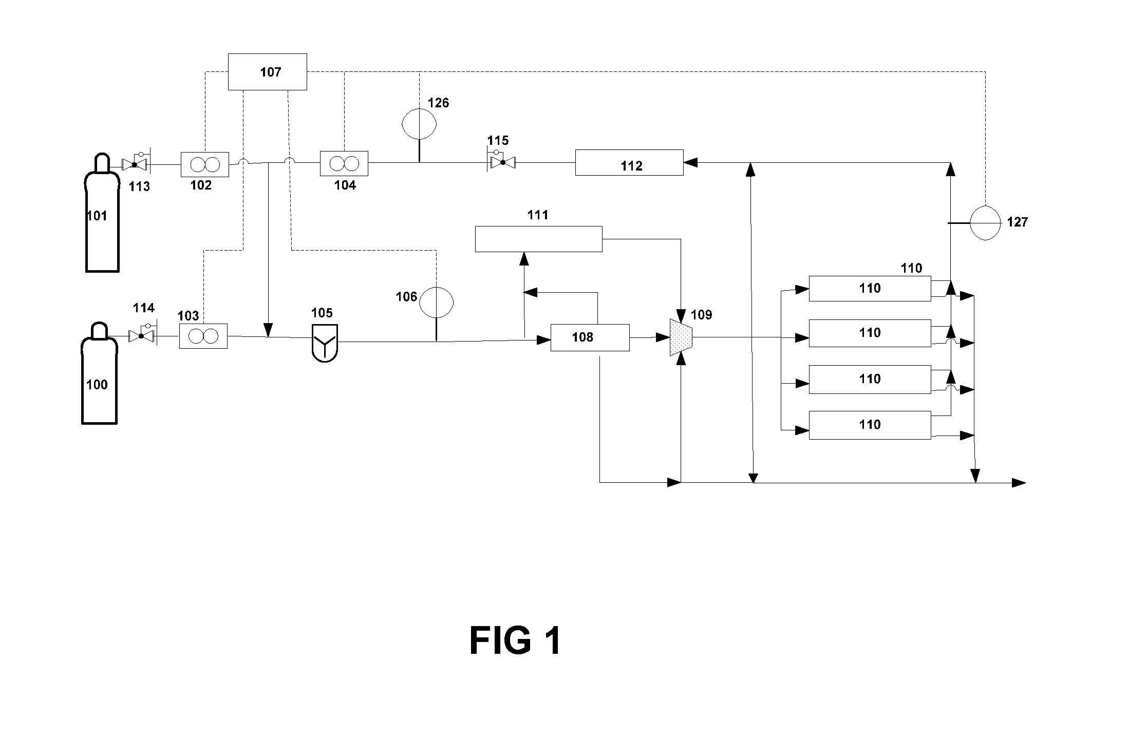
[0015]As used herein, all concentrations are expressed as volumetric percentages. One aspect that embodies the principles of the present invention will now be described. FIG. 1 shows a process flow diagram of an on-site dynamic blending system. As will be explained, the system of FIG. 1 is designed to dynamically blend gas mixtures with the capability to re-blend off-spec gas by recycling a flow rate of off-spec gas upstream of a mixer with a regulated flow rate of balance gas and active gas.

[0016]The supply gas sources for the balance gas and the active gas are designated as balance gas source 100 and active gas source 101, respectively. Each of the two gas sources 100 and 101 may be contained in a variety of different vessels such as, by way of example, ISO containers, drums, ton containers, tubes, or cylinders.

[0017]H2 or other gases may be used as the balance gas contained in balance gas source 100. A variety of active gas sources as known in the art may be utilized, such as, fo...


PUM

PropertyMeasurementUnit
pressureaaaaaaaaaa
concentrationaaaaaaaaaa
off-spec concentrationaaaaaaaaaa

Abstract

This invention is directed to various protocols for reprocessing off-spec gas to produce a concentration of off-spec gases to a desired target concentration. A combination of source gases is blended with the off-spec gas. This technique has the effect of enabling relatively small adjustments to the concentration of off-spec gas. Processes are also described that incorporate the blending protocols.

Description

FIELD OF THE INVENTION[0001]This invention relates to a method for re-blending off-spec gases.BACKGROUND OF THE INVENTION[0002]The blending of two or more gases to form a predetermined homogeneous gaseous mixture is fundamental to many industrial processes. As an example, the solar and LCD industries currently rely on the use of dilute dopant gas mixtures for doping semiconductor materials, and the like.[0003]The semiconductor industry continues to maintain an ever-increasing demand for ultra-high purity gases employed in a variety of fabrication processes. Many of the process gases utilized within the semiconductor industry are hazardous. By way of example, arsine, germane, phosphine, and silane are commonly employed gases within the semiconductor industry and are commonly referred to as active gases (“active gas”). These active gases are routinely blended with a balance source gas (“balance gas”) to create a resultant gas mixture (“product gas”) that can be used for a variety of p...

Claims


Application Information

Patent Timeline
Patent Type & Authority Applications(United States)
IPC IPC(8): F15D1/00B01F23/10
CPCG05D11/138B01F3/028Y10T137/0318B01F23/191G05D11/13B01F23/10
Inventor SONG, XUEMEIBROWN, LLOYD ANTHONYSCHULTE, THOMAS
Owner PRAXAIR TECH INC
Learn More