Wheel deburring device and deburring method
a deburring device and wheel technology, applied in metal-working equipment, polishing machines, manufacturing tools, etc., can solve the problem that the deburring device does not have this function at presen
- Summary
- Abstract
- Description
- Claims
- Application Information
AI Technical Summary
Benefits of technology
Problems solved by technology
Method used
Image
Examples
Embodiment Construction
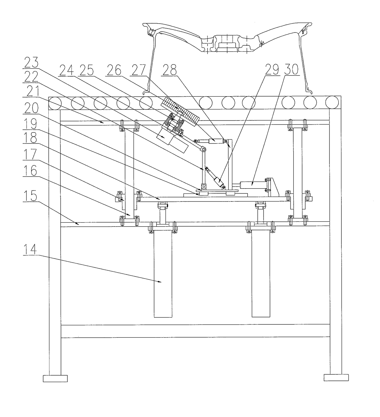
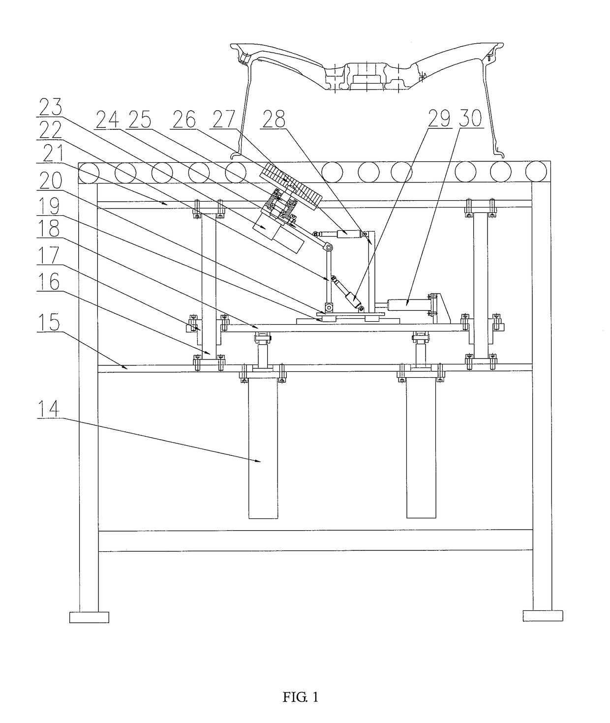
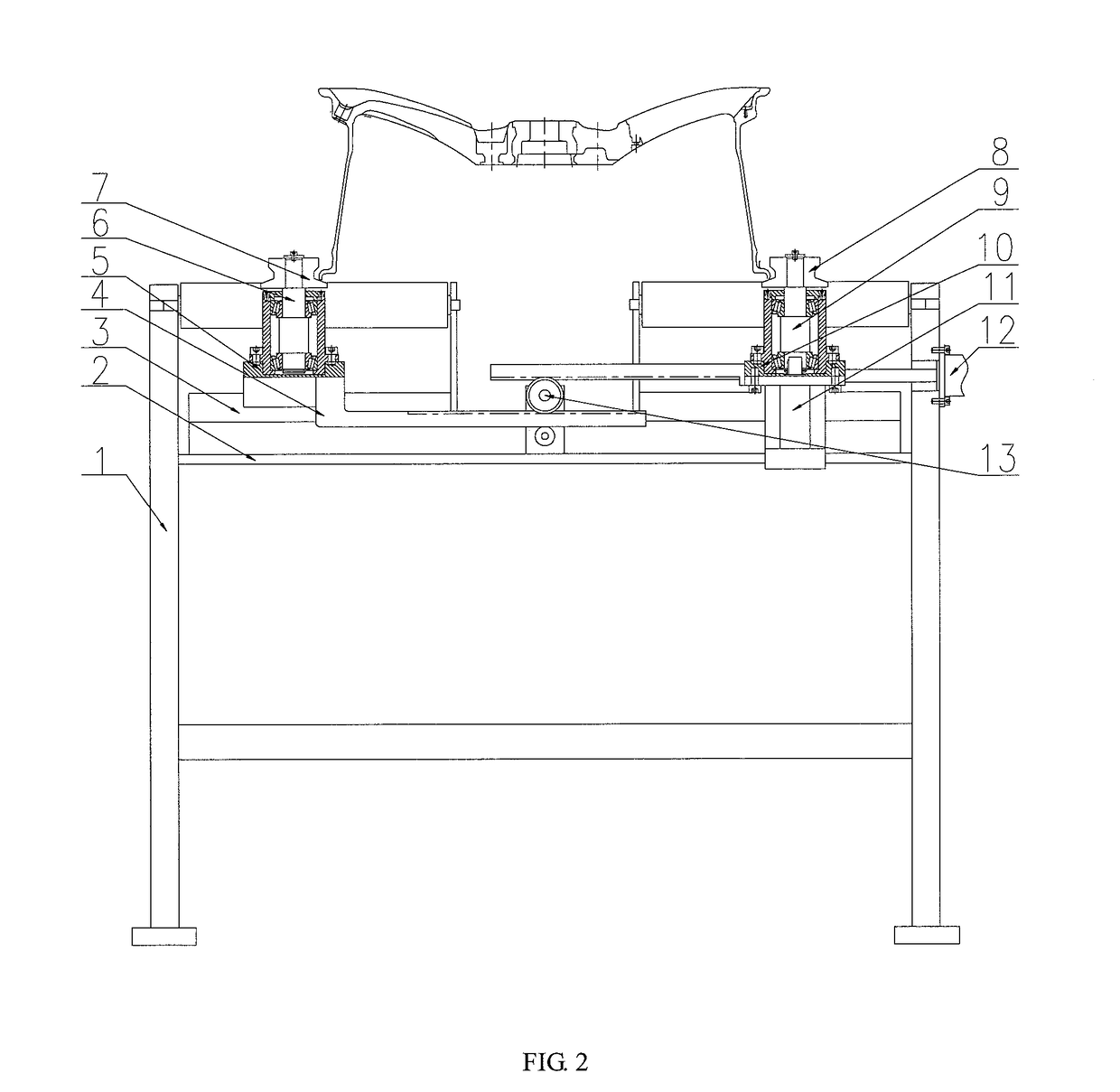
[0015]Details and working conditions of a specific device provided by the present invention will be illustrated below in combination with the accompanying drawings.
[0016]The device is composed of a frame 1, a medium plate 2, a synchronous guide rail 3, a gear rack 4, a left sliding plate 5, a left shaft 6, a left roller 7, a right roller 8, a right shaft 9, a right sliding plate 10, a servo motor 11, a clamping cylinder 12, a gear 13, a lifting cylinder 14, a lower plate 15, a guide post 16, a guide sleeve 17, a lifting plate 18, a translation guide rail 19, a translation bottom plate 20, an upper plate 21, a swing plate I 22, a motor 23, a swing plate II 24, a driving shaft 25, a hairbrush 26, a servo electric cylinder I 27, an upright post 28, a servo electric cylinder II 29 and a servo electric cylinder III 30. The synchronous guide rail 3 above which the left sliding plate 5 and the right sliding plate 10 are fixed is fixed above the medium plate 2; the gear racks 4 are fixed be...
PUM
 Abstract
Description
Claims
Application Information
 - R&D
- Intellectual Property
- Life Sciences
- Materials
- Tech Scout
- Unparalleled Data Quality
- Higher Quality Content
- 60% Fewer Hallucinations
Browse by: Latest US Patents, China's latest patents, Technical Efficacy Thesaurus, Application Domain, Technology Topic, Popular Technical Reports.
© 2025 PatSnap. All rights reserved.Legal|Privacy policy|Modern Slavery Act Transparency Statement|Sitemap|About US| Contact US: help@patsnap.com


