Filter-drier unit for refrigerant circuits

Inactive Publication Date: 2008-08-28
DANFOSS AS
View PDF14 Cites 3 Cited by
  • Summary
  • Abstract
  • Description
  • Claims
  • Application Information

AI Technical Summary

Benefits of technology

[0017]On the other hand, the proposed filter-drier arrangement can under certain circumstances considerably reduce the flow resistance, to which the passing refrigerant flow is exposed. This again causes that, compared to the known filter-drier arrangements; the pressure drop can be considerably reduced. This is possible, even though the filter-drier arrangement does not, or at least to a reduced extent, have to be enlarged.
[0028]A particularly advantageous embodiment occurs, if the size, the fixing and the resiliency of the filter arrangement are chosen so that, in connection with a flow of refrigerant through the filter arrangement, the filter arrangement is resiliently deformed in such a manner that at least one cavity is formed between the filter arrangement and an adjacent supporting surface. In this way, the arrangement can be designed so that during the flow through the filter-drier arrangement a refrigerant flow is generated, of which a part of the refrigerant flows into the cavity, that is, into a hollow. The impurities taken along by the refrigerant are thus forced into the formed cavity. The cavity can thus act as pick-up for the impurities trapped by the filter arrangement. When, after turning off the system, the filter arrangement resiliently reassumes its shape, the impurities gathered in the cavities can be retained. The exposed area of the filter arrangement can thus be kept free of impurities, so that a particularly low pressure drop of the filter-drier arrangement can be supported.

Problems solved by technology

Such particles have to be filtered away, as otherwise they could obstruct the circuit or cause an increased wear of the components.
A further contamination of the refrigerant occurs by the releasing of substances, which diffuse into the refrigerant circuit.
As traditional refrigerants are heavily hygroscopic; water turns out to be particularly problematic in this connection.
Water dissolved in the refrigerant can reduce the performance and efficiency of the system and additionally cause internal corrosion.
A major problem with such filter-drier units is to combine a good filtering and drying effect, a small pressure drop of the circulating refrigerant during operation of the refrigerant circuit, low costs and the smallest possible dimensions of the filter-drier unit.
During operation of the refrigerant circuit this causes a high pressure drop of the refrigerant in the area of the filter-drier unit.
This causes correspondingly large dimensions of the filter-drier unit and correspondingly high costs.

Method used


Image

  • Filter-drier unit for refrigerant circuits
  • Filter-drier unit for refrigerant circuits
  • Filter-drier unit for refrigerant circuits

Examples


Embodiment Construction

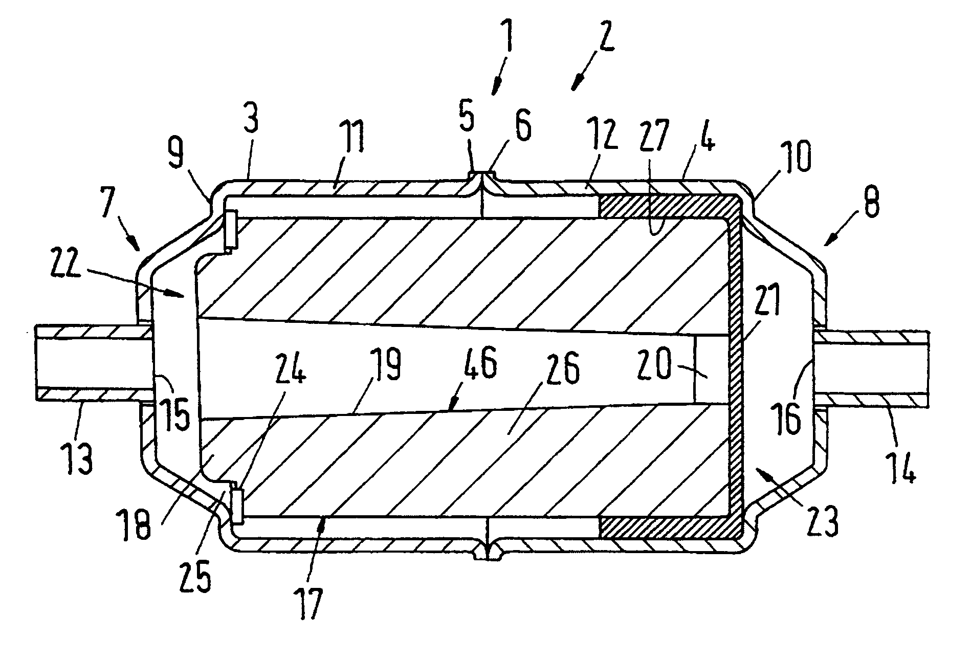
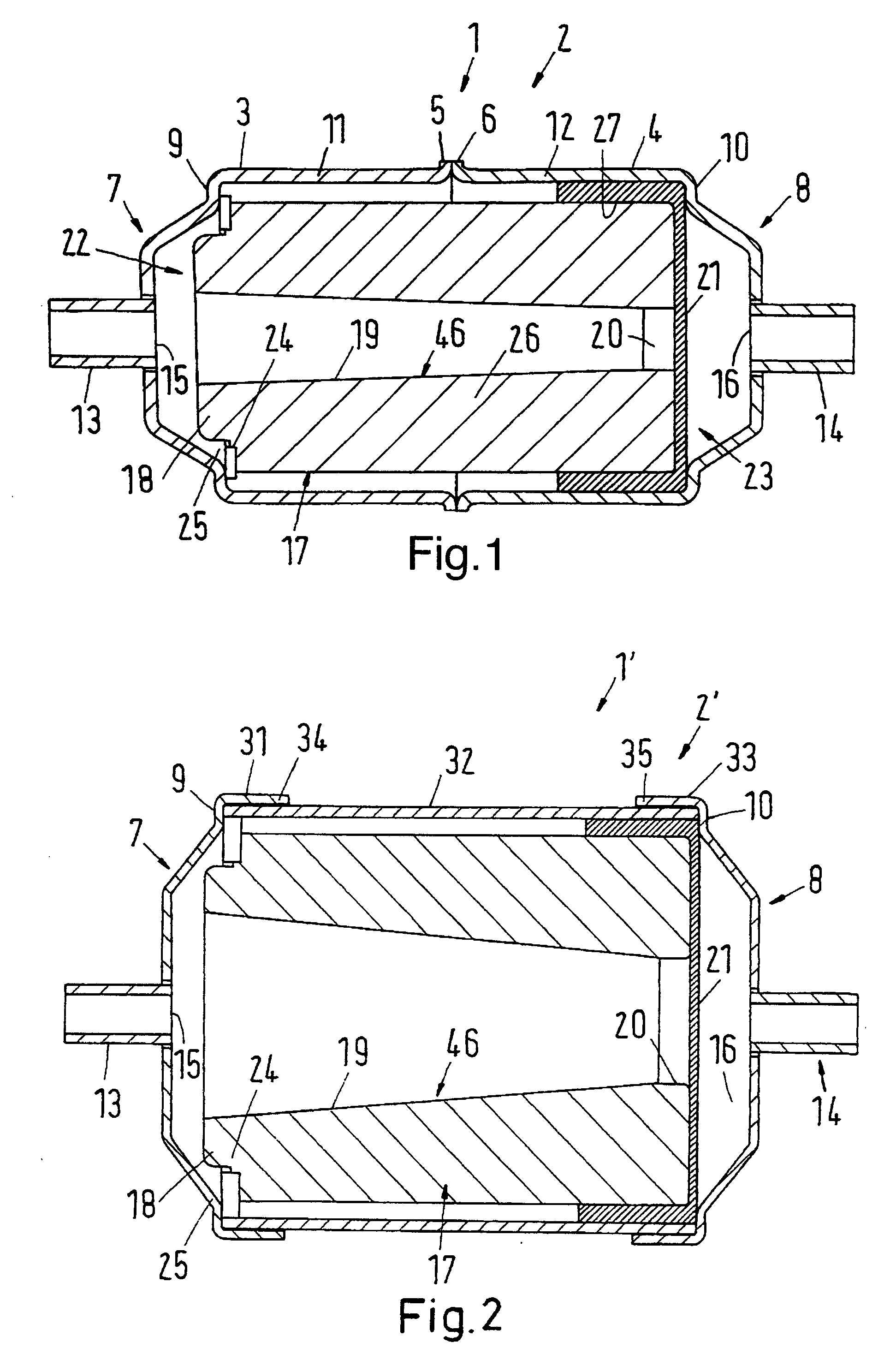
[0039]FIG. 1 shows a first embodiment of a combined filter-drier case that can, for example, be used for the refrigerant circuit of vehicle air-conditioning systems or domestic refrigeration or freezing appliances. In the embodiment shown in FIG. 1, the housing is made of two identical, cup-shaped housing parts 3, 4. One end of each of the two housing halves 3, 4 has a projection 5, 6. The projection 5, 6 enables a simple fluid-tight connection with the respective other housing part 3, 4.

[0040]At the respective other end of each housing part 3, 4, facing the projection 5, 6, a tub shaped housing bottom 7, 8 is provided. In the centre of each housing bottom 7, 8 a circular recess 15, 16 is provided, into which a connection tube 13, 14 is inserted and connected in a fluid-tight manner with the housing bottom 7, 8. Between the housing bottom 7, 8 and the cylindrically shaped cup area 11, 12 of the respective housing part 3, 4 is provided a ring-shaped, circumferential support 9, 10. Th...


PUM


Abstract

In known filter-drier cases for refrigerant circuits, the refrigerant flows through filter and drying means in a serial manner. During operation of the refrigerant circuit, this causes an undesirably large pressure drop. It is the task of the invention to provide an improved filter-drier arrangement (1, 1′) with a smaller pressure drop. For this purpose, it is proposed to design the filter-drier arrangement so that a part of the refrigerant flows in parallel through the filter (21, 43) and the drying means (17, 43).

Description

CROSS REFERENCE TO RELATED APPLICATIONS[0001]Applicant hereby claims foreign priority benefits under U.S.C. § 119 from German Patent Application No. 10 2007 009 760.5 filed on Feb. 27, 2007, the contents of which are incorporated by reference herein.FIELD OF THE INVENTION[0002]The invention concerns a filter-drier system for refrigerant circuits with at least one drier arrangement and at least one filter arrangement. Further, the invention concerns a refrigerant circuit with at least one drier arrangement and at least one filter arrangement for the refrigerant.BACKGROUND OF THE INVENTION[0003]Refrigeration systems, air-conditioning systems and heat pumps are commonly used for very different applications. The presently most frequent design of such systems is the so-called compression refrigeration machine, in which a refrigerant is pumped in a closed circuit by a compressor. The compressor and an expansion member divide the circuit into an area with refrigerant under higher pressure ...

Claims


Application Information

Patent Timeline
IPC IPC(8): F25B43/00
CPCF25B43/003
Inventor MUNOZ, NESTOR E. CABRERAGUTIERREZ, SERGIO URIBE
Owner DANFOSS AS
Why Eureka
Try Eureka